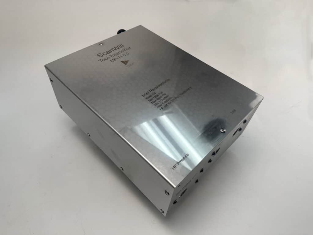
Tool Intensifier
MP-TI-5.0
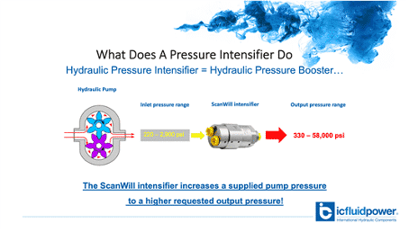
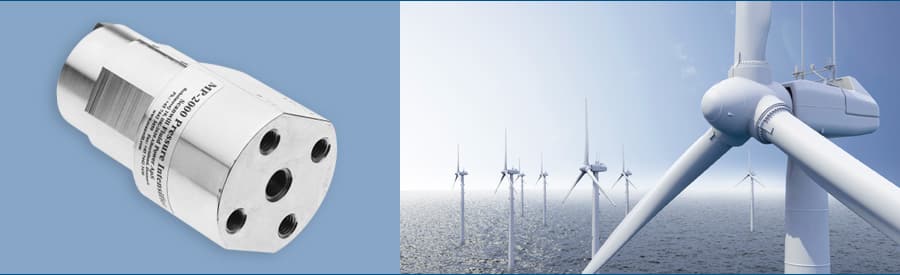
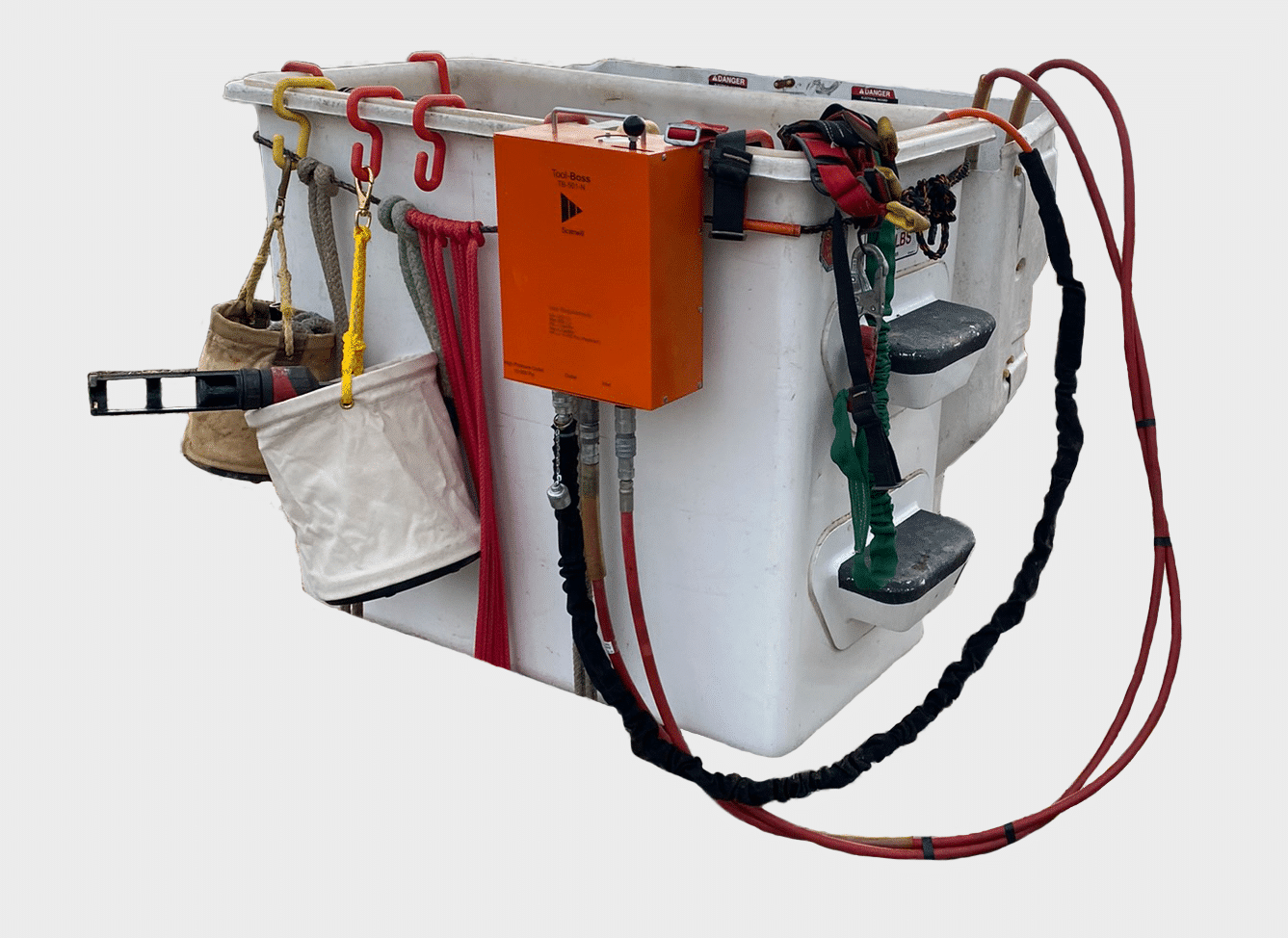
The tool intensifier is a device that intensifies the available hydraulic pressure from your truck to power your 10,000 psi hydraulic tools. It is designed for simple, one-handed operation, with a pressure gauge for consistent results, every time.
Learn more about the tool intensifier’s functions, benefits, and more.
Tool Intensifier Features
“Designed for Continuous Use and a Long Service Life”
High Max Operating Pressure
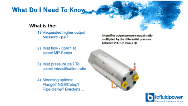
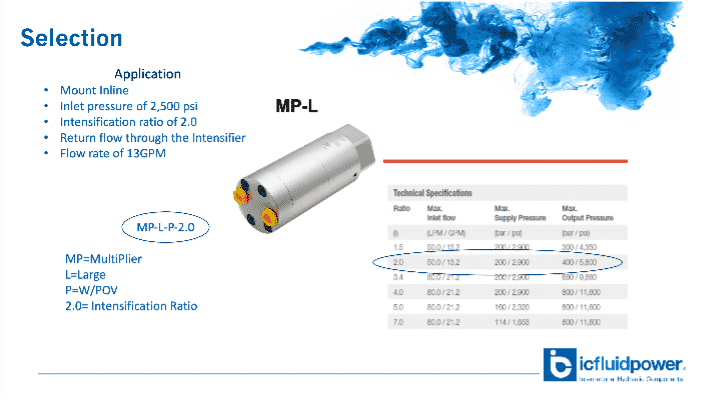
Boosts the hydraulic tool circuit in utility trucks, with an inlet pressure as low as 1,850 psi
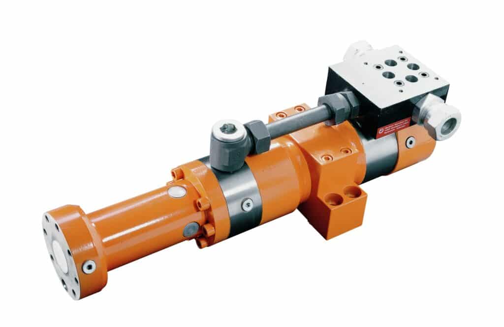
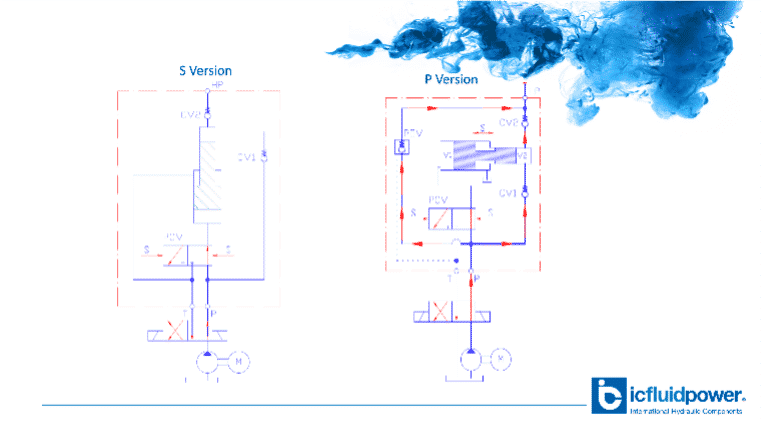
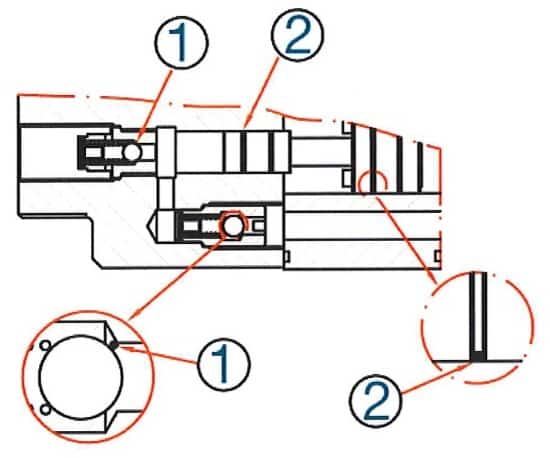
Designed with Built-in Functions
Contains pressure intensifier, single acting control valve, pressure regulator, and safety relief valve
Continuous Usage and Life in the Field
Can be used continuously without having to cool down during the day
High Level of Precision
Measure crimp head pressure easily with a built-in pressure gauge
Simple, One-Handed Operation
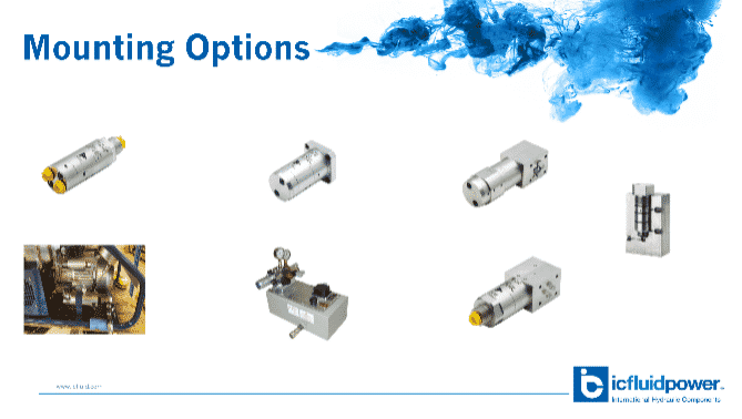
Easily secures to bucket with adjustable mounting brackets
Fast and Advanced Return Times
Designed for fast duty cycles with back pressures up to 700 psi
Try the Tool Intensifier Risk-Free
We’re so sure that you’ll love the hydraulic Tool Intensifier, we’ll let you try it at no cost.
3 Ways the Tool Intensifier Makes Your Job More Efficient
We’re confident that the tool intensifier will make a difference in your day-to-day. Reach out to a specialist to arrange a risk-free demo so you can see the difference for yourself!
Hydraulic Tool Intensifiers


What are Tool Intensifiers?
The tool intensifier utilizes the existing circuit on utility trucks and boosts it to 10,000 psi, allowing you to use large crimping tools without the need for a separate HPU.
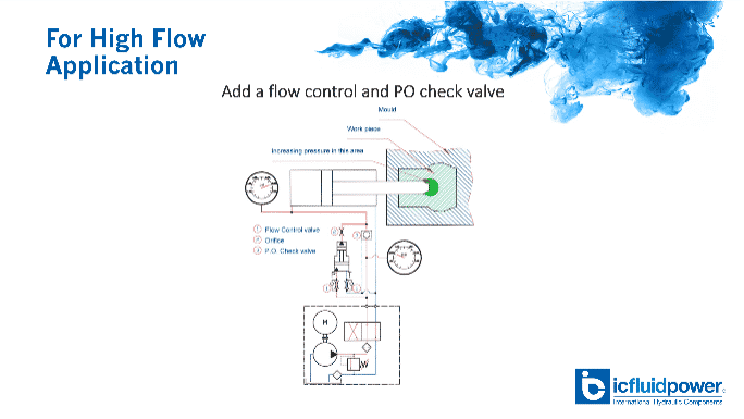
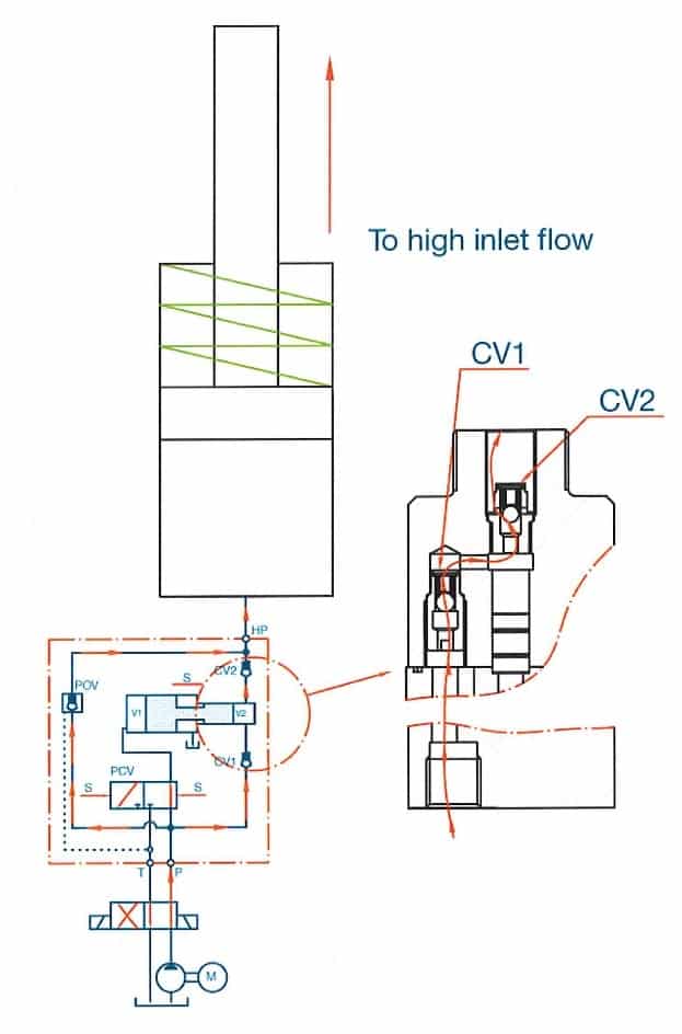
How do Tool Intensifiers work?
The pressure is intensified with a reciprocating piston that operates at full flow until the crimper bottoms out. Once the tool has bottomed out, the intensifier senses this and starts intensifying the lower pressure flow to 10,000 psi.
The tool intensifier plugs directly into your truck’s line. This eliminates the need for an alternate power source, such as batteries that need to be frequently recharged and can be limited to 50 crimps at a time.
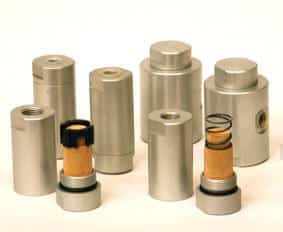
Tool Intensifier Features:
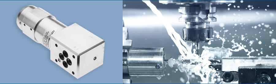
The hydraulic intensifier was thoughtfully engineered for the transmission and construction industry.
Built for continuous, full-day applications: The biggest advantage of the tool intensifier is the way it creates pressure. Due to smart construction of the intensifier design, the device does not build up heat fast and can be used continuously.
Precise crimps through simple pressure monitoring: The integrated pressure gauge makes it easy to validate when the 10,000 psi threshold is met, ensuring a perfect crimp.
Tool Intensifier Features:
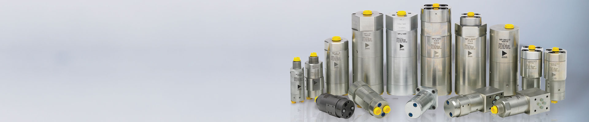
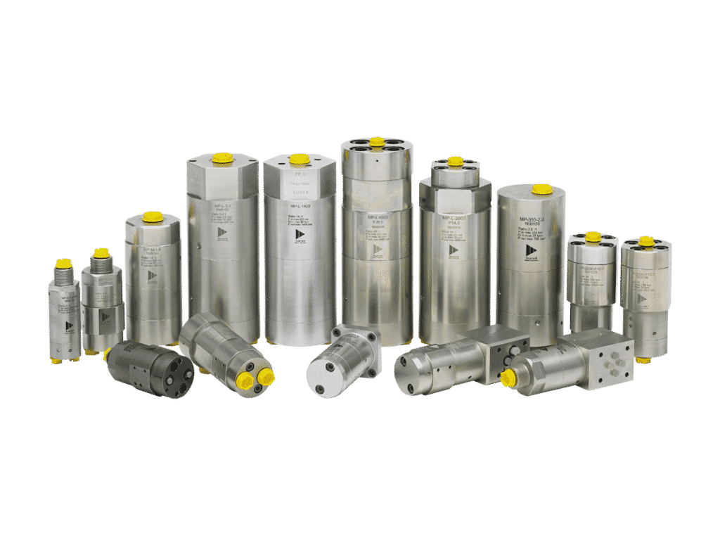
ScanWill is a supplier and tool intensifier manufacturer for various applications including construction, mechanical, and industrial.
Specifications
The tool intensifier is primarily designed for utility trucks up to 10,000 psi.
The specifications down below reflect our most recent model.
| Min Inlet Pressure | 1,850 psi (128 bar) |
| Min Inlet Flow | 0.8 GPM (3 LPM) |
| Max Backpressure | 700 psi (48 bar) |
| High Pressure Output Port (HP) | 3/8″ NPT |
| Low Pressure Inlet Port | 3/8″ NPT |
| Tank Return Port | 3/8″ NPT |
| Control | Single-acting spring return *Double-acting available in the future |
| Mounting Brackets | Included (Adjustable) |
| Couplings | Not Included (Available as an accessory) |