
Back to the Basics: Rotary Actuator Designs, Hytorc Valve FAQs, New Vertical Safety Catcher, and More…
August 12, 2026
Where Hydraulic Rotary Actuator Designs Perform Best
Hytorc Valves & Compensators FAQs
ScanWill Pressure Intensifier Case Study
A New Clamping Unit Product Line Addition

Where Hydraulic Rotary Actuator Designs Perform Best: Helical Spline, Rack and Pinion, & Vane
Rotary actuators are used wherever a load has to turn, pivot, steer, or swing into position. There are 3 main types of hydraulic rotary actuators, each characterized by differences in design and use cases.
|
Helical Spline |
Rack and Pinion |
Vane Style |
|
|
Typical Rotations |
Full 360° or intermediate angles* |
Full 360° or intermediate angles* |
90, 180°, 270° or intermediate angles |
|
Benefits |
Compact, lightweight, high-power density, mostly maintenance free, good load control |
Exceptional torque generation |
Exceptional torque generation, high rotation speed |
|
Downsides |
Most expensive |
Heavy, and large complex design; moderate maintenance |
Hard to seal, frequent leakage; limited rotation; moderate maintenance |
|
Popular Applications |
Mobile, Heavy Duty |
Industrial, Heavy Duty |
Dynamic Testing, End to End Rotation |
|
Cost |
High cost |
Medium cost |
Low cost |
*Rotation can be higher in special cases
Helical Spline Rotary Actuators
Helical spline actuators utilize a piston and a helix to create rotation up to 360°*.
As the piston strokes, the splined teeth convert linear motion into rotation. Since the splines are machined into both the piston and internal components (like the ring gear and shaft), the moving parts are tightly meshed together. This design creates very high torque using the least space as possible.
As a result, helical spline actuators are typically considered when applications need to optimize space and weight, like in mobile equipment. On a forest harvester, for example, the actuator can be mounted directly where the boom connects to the grapple or the harvesting head. Here, it can rotate up to 360°*, allowing the operator to stem and process logs without repositioning the vehicle.
All internal moving parts are constantly lubricated by oil maintaining wear. However, bearings and seals are wear items that will need periodic replacement.
Helical spline actuators are also suited for heavy-duty applications, like mining rigs and construction excavators. Because all moving parts are fully enclosed within a housing, the device is protected from dust and debris.
Design features
Rack and Pinion Actuators
Rack and pinion actuators use a traditional design that creates rotation using one or two pistons with a row of gear teeth (or rack) machined into it. As the piston strokes, the rack engages the pinion, causing the outer shaft to rotate.
Because the piston has a large surface area, the fluid creates very high linear force, which then translates into substantial torque. This is perfect for demanding applications that require heavy duty industrial applications and material handling.
In valve actuation, specifically for quarter-turn valves like ball and butterfly valves, sufficient torque is required to exceed seat friction, sealing forces, and differential pressure. Rack and pinion actuators are commonly selected in these applications because they can generate enough torque to overcome these factors.
While rack and pinion actuators provide exceptional performance, their mechanical design includes multiple seals, bearings, and sliding interfaces that wear and degrade with time. In high‑cycle or harsh environments, piston seals, O‑rings, and slide guides may need periodic inspection and replacement to control leakage.
Design features
Vane Rotary Actuators
Unlike the former types, vane style actuators rotate shorter distances, often 90° or 180°, though some designs can extend as far as 270° depending how many vanes are used. Vane actuators are designed with a sealed chamber which fills up with oil. As oil pushes the vanes inside the housing around, the central shaft rotates.
Multiple vanes can be added inside the actuator to increase the torque without increasing the operating pressure. However, this design tradeoff reduces the available rotation angle, as each additional vane divides the internal chamber into smaller segments and limits angular travel.
Similar to rack and pinion designs, vane actuators can generate high rotational force. This is optimal for highly dynamic, high-frequency applications like torsion or pulse testing, where rapid, repeatable motion is required.
Vane actuators are also highly effective in automated indexing processes where the cylinder strokes end to end. For example, in a conveyor transfer, a vane actuator may be used to swing a deflector arm, which guides products from one line to the next.
One limitation of the vane design is sealing. The vane seals slide against the housing, so a small amount of fluid always bypasses them from the pressurized side to the low-pressure side. This internal leakage is inherent to the design, not a defect, and it is accounted for in the actuator’s efficiency rating.
Design features
View our new introduction to rotary actuator page.




What You Should Know About Hytorc and Their Products
Below are some questions we often get about our hydraulic accessory manufacturer, Hytorc, and their products.
1. Who is Hytorc and how are they connected to the HYTORC that is based in the US?
Hytorc Technologies sells high-quality hydraulic products and components. Previously known as HydroWer and also referred to as just Hytorc, they are a company based in Sprockhövel, Germany. In 2012, HYTORC took over HydroWer-Hydraulics GmbH, and the name was changed to Hytorc Technologies in 2017.
The difference also lies in the parts sold by each company. The US-based HYTORC sells torque wrenches, fasteners, hydraulic pumps, tensioners, and other bolting tools. In comparison, Hytorc Technologies mainly sells components such as valves, compensators, couplings, and other hydraulic accessories.
2. What is the relationship between Hytorc Technologies and IC-Fluid Power?
In 1989, IC-Fluid Power became the sole US distributor of Hytorc Technologies’ hydraulic product line. IC-Fluid Power serves as the link between the North American market and the high-quality valves, accessories, and other components. IC-Fluid Power does not distribute HYTORC bolting tools and related items. Today, the relationship between the companies allows for quick distribution of popular products (such as the hydraulic butterfly valves and rubber compensators) due to their local inventory in IC-Fluid’s Ohio warehouse. IC-Fluid Power also offers local engineering support and handles all international logistics, including communication and shipment.
3. How do Hytorc butterfly (shut-off valves) improve safety and maintenance?
Butterfly valves are a more compact alternative to the traditional ball valve and improve safety and maintenance by offering a quick and easy way to isolate flow on low-pressure lines. This function has two primary benefits.
1. Safety
In the case of a component failure, the butterfly valve isolates flow from the reservoir to prevent large hydraulic oil spills that can result in safety hazards for the equipment, workers, and the environment.
2. Maintenance
For suction lines requiring regular maintenance, the butterfly valve provides an easy way to stop the flow of hydraulic oil, so that the reservoir does not need to be drained, saving time and streamlining maintenance.
4. What do rubber compensators do in a hydraulic system?
In short, rubber compensators protect your system in a handful of ways: absorbing vibrations, damping noises, and compensating for movement in axial and transverse directions. These are used on low-pressure suction lines up to 116 psi (8 bar).
Hytorc created these compensators for applications that are subject to unwanted vibrations from pressure and flow fluctuations, physical movement in mobile equipment, and regular operation of pumps and motors. They are especially important in systems with high-vibration systems and hard piping and can be seen across industries like oil and gas, mining, marine, industrial manufacturing, construction, and transportation.
5. What makes Hytorc check valves different?
Hytorc check valves differ from traditional check valves in two main ways:
1. Higher Pressure Capabilities
Most competitors are limited to a maximum pressure allowance of 3,000 psi, but Hytorc check valves are suitable for high-pressure applications up to 10,000 psi.
2. More Compact Installation
In applications where saving space is critical, a Hytorc check valve can make a difference. Their unique half-ball design maximizes space, while still creating a perfect seal to block reversed flow.

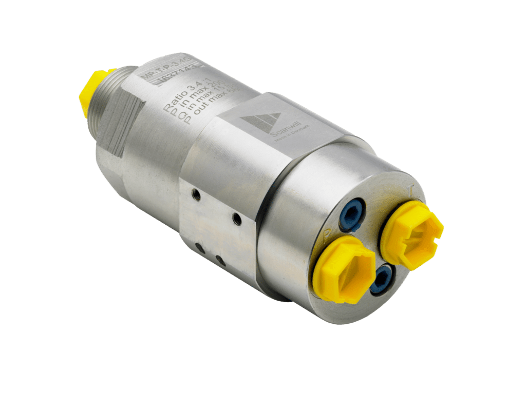
This photo was sourced from ScanWill’s official website.
Diprax Integrates ScanWill Pressure Intensifier for Isolated Pressure Boosts
Diprax provides advanced hydraulic solutions, offering components, system design, and engineering support for industrial applications. They focus on tailored hydraulic systems that meet complex operating requirements without adding unnecessary size or cost.
For systems that only require high pressure for specific functions on a circuit, and not throughout the entire cycle, Diprax utilizes ScanWill’s pressure intensifiers, as opposed to increasing the entire system’s pressure. In one application, an MP-T in-line intensifier was used with an intensification ratio of 1:4 to boost targeted pressure from 175 bar (2,500 psi) to 700 bar (10,150 psi). Therefore, the rest of the system remains at a lower pressure level, meaning no need to redesign or oversize the entire system.
MP-T Technical Specifications
Why Diprax Chose ScanWill Pressure Intensifiers
By adding high-pressure capabilities only where it is needed, Diprax achieves several benefits. They add precise, focused pressure control; the space requirement of the system is reduced compared to adding a new pump or overhauling the system; and the overall system cost is lowered via energy and investment costs.
“We chose Scanwill’s pressure intensifiers because of how simple, reliable, and compact the designs are. It’s easy to add them when higher pressure is needed.” – Mikel Martin, Technical Director, Diprax
Learn more about our most popular intensifier model.

New Safety Catcher for Vertical Axes
The hydraulic safety catcher is a new addition to Hänchen’s clamping unit product line and is designed as a safety component for vertical, gravity-loaded axes. It prevents unwanted sinking when pressure or power is lost via a mechanical, self-energizing principle. As the load attempts to move downward, the clamping system generates force automatically to lock. The main purpose of this clamping unit is to protect people, machines, and systems from damage during failure.
Where the Safety Catcher is Used
Safety catchers are used wherever a sinking axis could create a serious safety hazard due to a power failure, line break, or control error. This includes applications such as:

Safety Catcher vs Ratio-Clamp
Both the safety catcher and the Ratio-Clamp are clamping units for round rods, but they are optimized for different roles within the machine. The safety catcher’s main purpose is protection and it is specifically designed for vertical axes, while the Ratio-Clamp’s main purpose is functional holding and it is designed for both horizontal and vertical axes.
To better understand the difference, let’s look at how each device behaves under load. Because of its safety functionality, the safety catcher is designed to hold very heavy loads. During its holding, the rod moves minimally before fully stopping. To release after locking, the safety catcher uses a counterstroke before continuing the motion. The Ratio-Clamp, in contrast, is designed to immediately stop the movement and then release via hydraulic power without any return movement. Thus, the Ratio-Clamp is ideal for precise, repeatable position holding, rather than emergency, protective holding of a sinking load.
|
Feature |
Safety Catcher |
Ratio-Clamp |
|
Primary purpose |
Protection for gravity-loaded vertical axes, prevents sinking during failure |
Functional clamping for positioning, holding, and securing of cylinders or rods in any mounting orientation |
|
Holding forces |
Very heavy loads |
Medium to heavy loads |
|
Load direction |
One load direction (downward on vertical) |
Both load directions (direction independent) |
|
Engagement condition |
Automatically activates when pressure or power fails; rod moves a short distance before fully locking |
Engages in the event of controlled or uncontrolled pressure drop, can be used for emergency failure as well; rod instantly locks |
|
Release behavior |
Requires release pressure and a return stroke (upward rod movement) to release holding |
Releases exactly at the locked position with hydraulic pressure only; no rod movement |
|
Typical applications |
Presses, injection molding machines, lifts, robotics, where safety certification is required, where vertical load failure is dangerous |
Roll-forming machines, grinding systems, test rigs, general industrial machinery, where precise positioning or holding is needed |