HYDRAULIC SERVO VALVES – S4 PRO

Hydraulic Servo Valves – S4 Pro
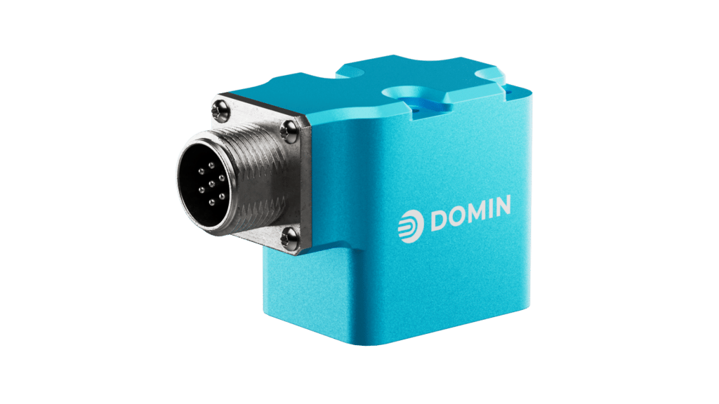
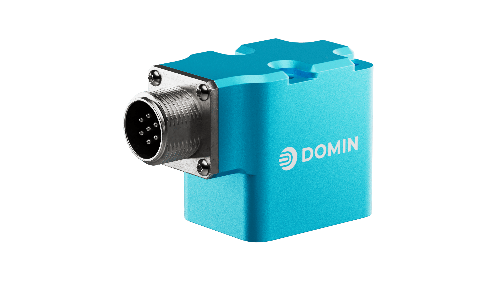
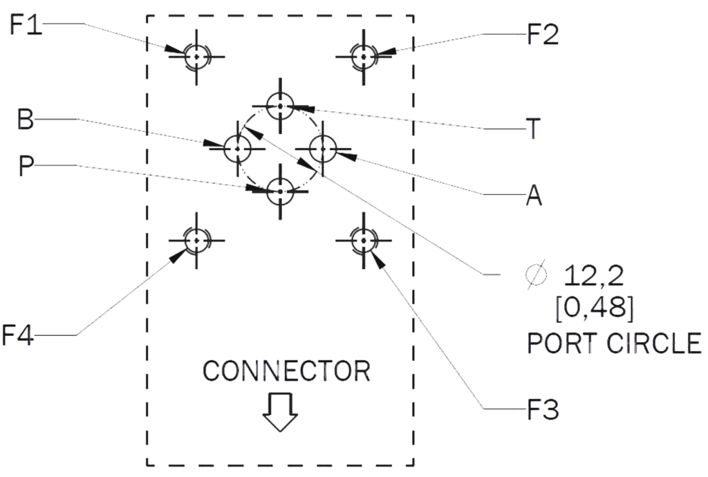
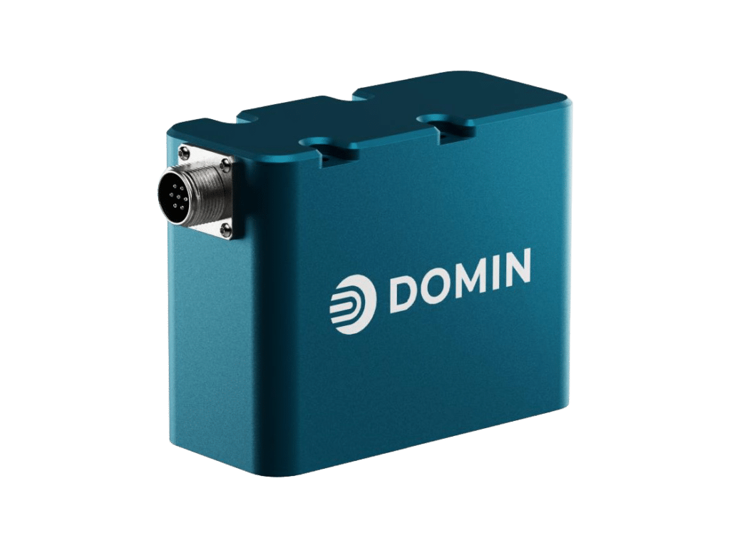
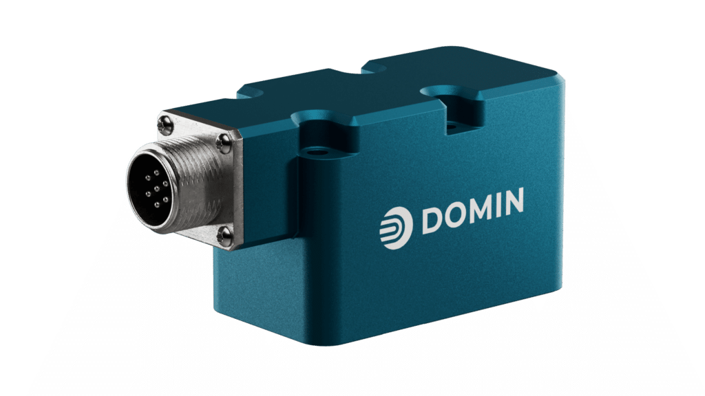
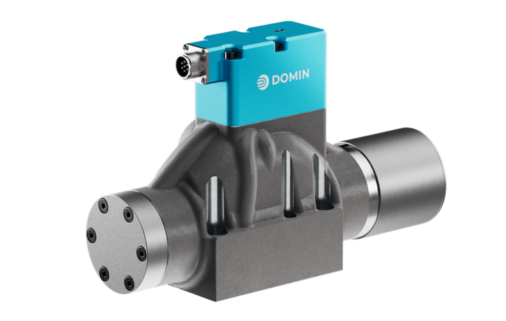
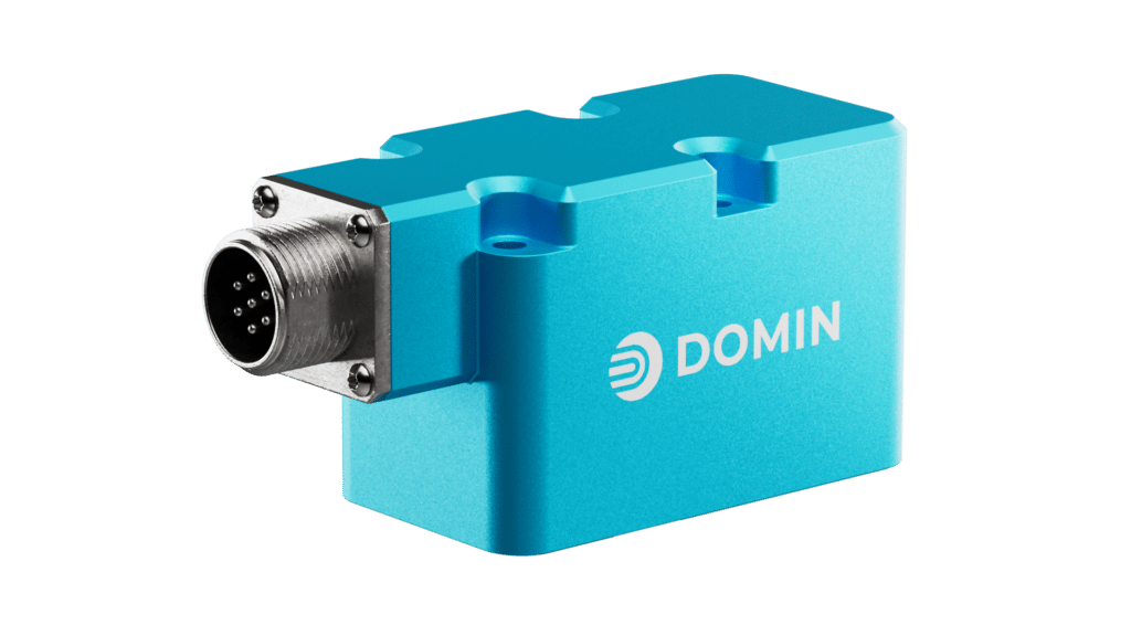
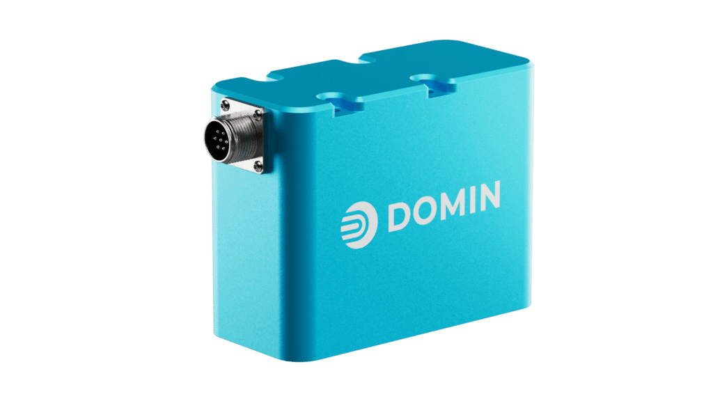
As the smallest direct drive valve in the world, the S4 Pro is a true game-changer. With its miniature port circle of 0.48 in (12.2 mm) and weight of less than 0.65lbs (300g), it’s perfectly suited for applications where space is limited but performance is paramount.
From demanding industrial settings to cutting-edge robotics and motorsport applications, the S4 Pro excels. Delivering superior performance, dynamics, and reliability in an ultra-compact package, it introduces a new era of control and productivity with the Domin S4 Pro series.
Available on S01 port pattern as standard.
Key Specs:
- Hysteresis: <1%
- Leakage: <0.12 gpm (<0.45 l/min)
- Mass: 0.64lbs (290g)
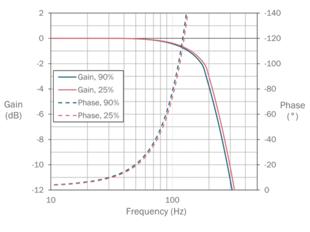
- Frequency Response: >200Hz
- Rated Flow: 0.2-5gpm (0.5-18 l/min)
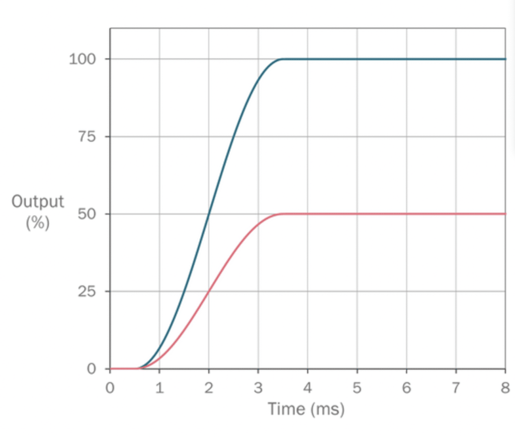
- Response Time: <3 ms
Key Features:
- Integrated electronics with spool position feedback
- Rated flow rate of up to 5gpm (18 l/min)
- Bandwidth of over 200 Hz
- Low power consumption of less than 2 W
- Miniature footprint (ISO 10372 size 01)
- Low weight of 0.64lbs (290 g)
Standard Modification Options:
- 6 different control methods
- 2 different hydraulic fluids
- 3 choices of seal material
- 4 choices of connector
Technical Data
Design | Direct Drive Servo Valve | |
Actuation | Rotary-Rotary | |
Size | Miniature | |
Mounting Interface | ISO 10372-01-01 | |
Ambient Temperature | ºC (ºF) | -20 to +60 (-4 to +140) |
Mass | kg (lb) | 0.29 (0.64) |
Vibration Resistance | g | 35, 3 axes |
Shock Resistance | g | 50 |
Max. Operating Pressure (P, A, B, T) | Bar (psi) | 350 (5,000) |
Fluid | Hydraulic Oil DIN 51524-535 | |
Fluid Temperature | ºC (ºF) | -20 to +80 (-5 to +175) |
Viscosity | cSt | 5 to 500 |
Rated Flow | l/min (US gal / min) | 0.5 to 6 (0.2 to 1.6) / 6 to 11 (1.6 to 2.9) / 11 to 18 (2.9 to 4.8) |
Flow Maximum | l/min (US gal / min) | 1.4 to 12 (0.4 to 3.2) / 12 to 22 (3.2 to 5.8) / 22 to 36 (5.8 to 9.6) |
Leakage at 100 bar | l/min (US gal / min) | <0.2 (0.05) / <0.45 (0.12) / <0.45 (0.12) |
Filtration | ISO 4406 (1999) 18/16/13 |
Response Time at 100% Step Input | ms | <3 |
Frequency Response (-3dB gain, ±25% signal) | Hz | >200 |
Frequency Response (-90deg phase, ±25% signal) | Hz | >110 |
Hysteresis | % | <1 |
Threshold | % | <1 |
Null Shift | % | <1 |
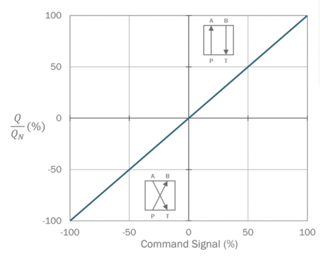
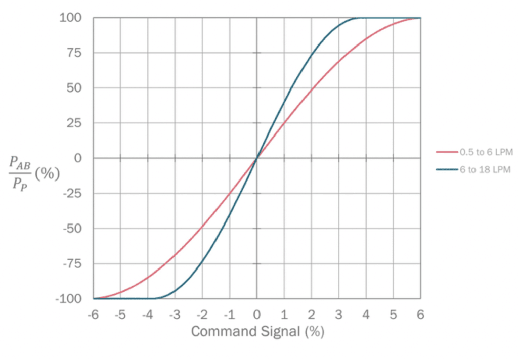
View performance graphs for the S4 Pro Domin Servo Valve below including Step Response, Flow vs Command, Frequency Response, and Pressure Gain:


Ratings of the valve electronics vary based on selected command input. Note that input ranges of Code E (±5 mA) are unavailable for S4 Pro.
Absolute Maximum Ratings* 11185_e4f368-7e> |
11185_758f8a-fd> |
Min. 11185_94a2e2-e9> |
Typ. 11185_c47cc0-9a> |
Max. 11185_c5efc6-69> |
Supply Voltage 11185_0d9f5c-81> |
V 11185_e4ec4b-7a> |
0 11185_7ff3e0-f7> |
– 11185_fea3a2-d6> |
30 11185_447d75-b1> |
Differential Input Signal 11185_22d62b-28> |
V 11185_384b1b-81> |
-10.5 11185_3f8fa9-57> |
– 11185_d2f110-2e> |
10.5 11185_3afb3e-97> |
Input Signal Common Mode Offset 11185_242dda-9e> |
V 11185_5b952c-16> |
-10 11185_b4e186-0a> |
– 11185_f76056-8c> |
10 11185_fb142f-e2> |
Normal Operating Conditions 11185_6f7ccf-9d> |
11185_e65614-5c> |
Min. 11185_bd1bdd-5c> |
Typ. 11185_f4bbfd-ef> |
Max. 11185_91cfa9-95> |
Supply Voltage 11185_90729d-76> |
V 11185_7a03ee-69> |
22 11185_1aa878-f5> |
24 11185_4fd9df-6b> |
30 11185_36a682-61> |
Peak Current Consumption** 11185_55c279-4e> |
A 11185_6218b3-ce> |
– 11185_e6c67b-dd> |
– 11185_258846-cc> |
3.3 11185_c58143-78> |
Differential Input Signals 11185_58ce60-fc> |
V 11185_f3deac-25> |
-10 11185_f2777e-c2> |
– 11185_9ce608-30> |
10 11185_a7b07a-9d> |
Input Impedance 11185_f57206-84> |
KΩ 11185_7adafc-44> |
200 11185_c33cc5-d2> |
– 11185_9c8bbf-86> |
– 11185_4c68eb-e8> |
Absolute Maximum Ratings* 11185_6efb2e-62> |
11185_766237-24> |
Min. 11185_bc063e-d7> |
Typ. 11185_2b753c-3a> |
Max. 11185_739a2f-17> |
Supply Voltage 11185_a8ea23-f7> |
V 11185_a5fa57-e4> |
0 11185_a94da2-10> |
– 11185_58ad8f-48> |
30 11185_a2d22a-da> |
Differential Input Signal 11185_824985-f3> |
mA 11185_7c812e-35> |
-25 11185_4e3570-3b> |
– 11185_bd5a5d-83> |
25 11185_8d241e-1f> |
Input Signal Common Mode Offset 11185_5f0faa-d2> |
V 11185_ff888d-b3> |
-10 11185_6f6e78-bf> |
– 11185_ecbb10-0b> |
10 11185_d27fc8-d2> |
Normal Operating Conditions 11185_f9c61e-13> |
11185_71501b-29> |
Min. 11185_c07a7f-31> |
Typ. 11185_5dfd94-99> |
Max. 11185_ee4362-2f> |
Supply Voltage 11185_1d3d16-0b> |
V 11185_3aaaa1-57> |
22 11185_d4e2a6-b9> |
24 11185_917a44-dc> |
30 11185_7a517e-f0> |
Peak Current Consumption** 11185_e7533e-56> |
A 11185_dd9b58-cb> |
– 11185_75aab1-9e> |
– 11185_eebfd2-6b> |
3.3 11185_89f0cd-46> |
Differential Input Signals 11185_2e88f7-b0> |
mA 11185_4415df-6d> |
20 11185_576dc9-87> |
– 11185_2e370a-1f> |
20 11185_3b2db1-bf> |
Input Impedance*** 11185_6d81b0-7a> |
Ω 11185_c75545-78> |
– 11185_9fc6c9-ae> |
392 11185_eceb45-65> |
– 11185_7a8031-7b> |
Absolute Maximum Ratings* 11185_9ebec3-d4> |
11185_dc60ef-ee> |
Min. 11185_93d0d5-04> |
Typ. 11185_03033c-8a> |
Max. 11185_88653e-d9> |
Supply Voltage 11185_5d9fa2-2e> |
V 11185_8a8fdc-bf> |
0 11185_e69894-08> |
– 11185_e4a7d8-89> |
30 11185_9e4a30-fb> |
Differential Input Signal 11185_56ca05-59> |
mA 11185_b05b40-b9> |
-25 11185_68ab0f-51> |
– 11185_fff02e-1e> |
25 11185_d31d3f-f8> |
Input Signal Common Mode Offset 11185_a8939c-a7> |
V 11185_431ac2-00> |
-10 11185_093f56-c3> |
– 11185_04ed40-66> |
10 11185_6ae103-1b> |
Normal Operating Conditions 11185_2bcbe2-cc> |
11185_40fdce-4b> |
Min. 11185_c33e92-6f> |
Typ. 11185_db28cd-49> |
Max. 11185_692fe7-bd> |
Supply Voltage** 11185_e551df-a9> |
V 11185_1e2791-71> |
22 11185_553036-ce> |
24 11185_5c2f73-c4> |
30 11185_40d9d3-87> |
Peak Current Consumption 11185_818537-c8> |
A 11185_4fca24-dd> |
– 11185_9f435d-16> |
– 11185_da269a-d1> |
3.3 11185_4d2a0b-58> |
Differential Input Signals 11185_ff8152-63> |
mA 11185_065a54-ca> |
4 11185_96cac2-68> |
– 11185_f01cce-5e> |
20 11185_5563b0-9b> |
Differential Input Signals for drive off**** 11185_6cc43c-cd> |
mA 11185_ac0ee9-da> |
-20 11185_942274-26> |
– 11185_599443-7a> |
2 11185_9aacca-6a> |
Input Impedance*** 11185_a4e92f-20> |
Ω 11185_8dc11d-98> |
– 11185_24949b-a1> |
392 11185_82100c-0a> |
– 11185_daa1a6-71> |
Absolute Maximum Ratings* 11185_186afc-92> |
11185_a31571-04> |
Min. 11185_b6a5f9-ab> |
Typ. 11185_41a2ca-df> |
Max. 11185_fae1f3-f1> |
Supply Voltage 11185_3bc169-ca> |
V 11185_9e66c2-52> |
0 11185_988874-f3> |
– 11185_7026b8-67> |
30 11185_123bc7-bf> |
Differential Input Signal 11185_2847e3-1a> |
mA 11185_691f25-26> |
-5.5 11185_8e9763-02> |
– 11185_014d7c-52> |
5.5 11185_9ce0f1-42> |
Input Signal Common Mode Offset 11185_88b7db-78> |
V 11185_672486-60> |
-5 11185_729207-90> |
– 11185_6b9f66-6a> |
5 11185_72da61-b4> |
Normal Operating Conditions 11185_83e8d8-52> |
11185_220b26-52> |
Min. 11185_d5a7fe-56> |
Typ. 11185_3ab39a-fc> |
Max. 11185_d9cfcc-01> |
Supply Voltage 11185_d61297-c5> |
V 11185_a05ba5-9b> |
22 11185_621ba7-b5> |
24 11185_ab4118-ef> |
30 11185_bbf9bd-4b> |
Peak Current Consumption** 11185_150da4-d7> |
A 11185_517bc8-d8> |
– 11185_0f53e5-de> |
– 11185_a40d8c-78> |
3.3 11185_2fa035-83> |
Differential Input Signals 11185_49caf1-39> |
mA 11185_a2b321-f6> |
-5 11185_fdc33d-09> |
– 11185_c00127-a0> |
5 11185_f55526-a7> |
Input Impedance 11185_f54811-d6> |
KΩ 11185_e91e50-56> |
200 11185_cab0c3-d9> |
– 11185_e00503-1a> |
– 11185_62317c-bc> |
* Conditions outside of the absolute maximum ratings may cause permanent damage to the valve. Operation of the product outside of the nominal operating conditions is not guaranteed and may affect product reliability.
** The valve supply must be protected with a 4 AT fuse or equivalent overcurrent protection device.
*** Valves with a current command signal use a 0.1% tolerance shunt resistor to measure demand current.
**** For 4 to 20mA command signal, a current in this range will disable the motor drive until a current outside this range is received at the command input.
Valves can be provided with an enable function. This allows the valve to be enabled or disabled by varying the voltage into the enable pin. Note that valves with code C command type can also be enabled or disabled using the command signal; see the corresponding table for further details.
Normal Operating Conditions 11185_06d49f-f9> |
11185_697d1a-31> |
Min. 11185_86f276-2f> |
Typ. 11185_787f54-ca> |
Max. 11185_0f33f9-38> |
Voltage for Drive Enable 11185_af2426-03> |
V 11185_168c3a-9f> |
9 11185_c44b9e-f2> |
– 11185_6e7d9d-49> |
28 11185_a0c2fc-48> |
Voltage for Drive Disable 11185_19b83d-4a> |
V 11185_5fd3a2-2a> |
0 11185_593a76-81> |
– 11185_464f93-3e> |
5 11185_f322ac-a1> |
Input Impedance 11185_c035a4-fe> |
Ω 11185_02c838-21> |
50 11185_1859a1-df> |
– 11185_fcdebc-3e> |
– 11185_c5cdeb-b1> |
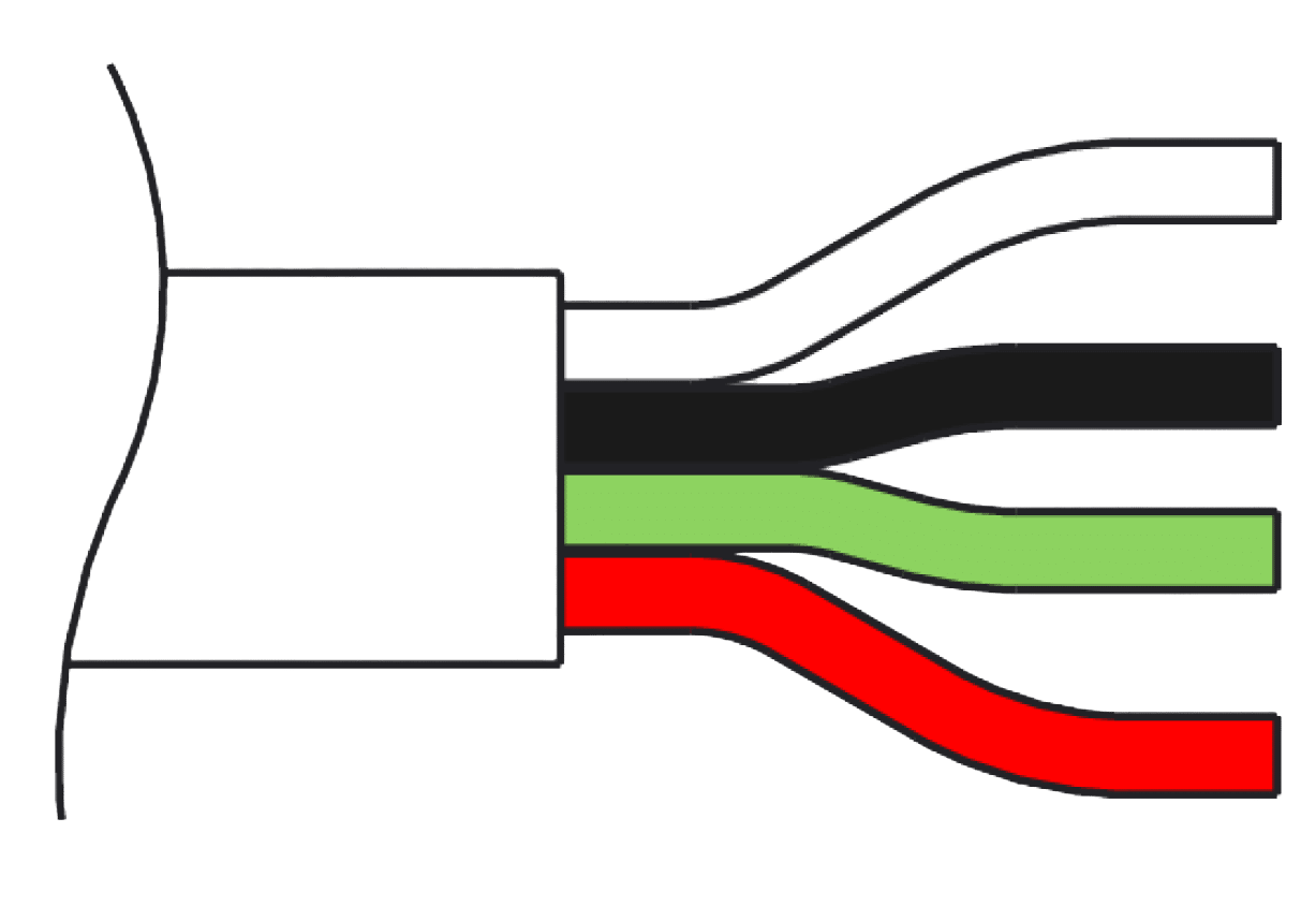
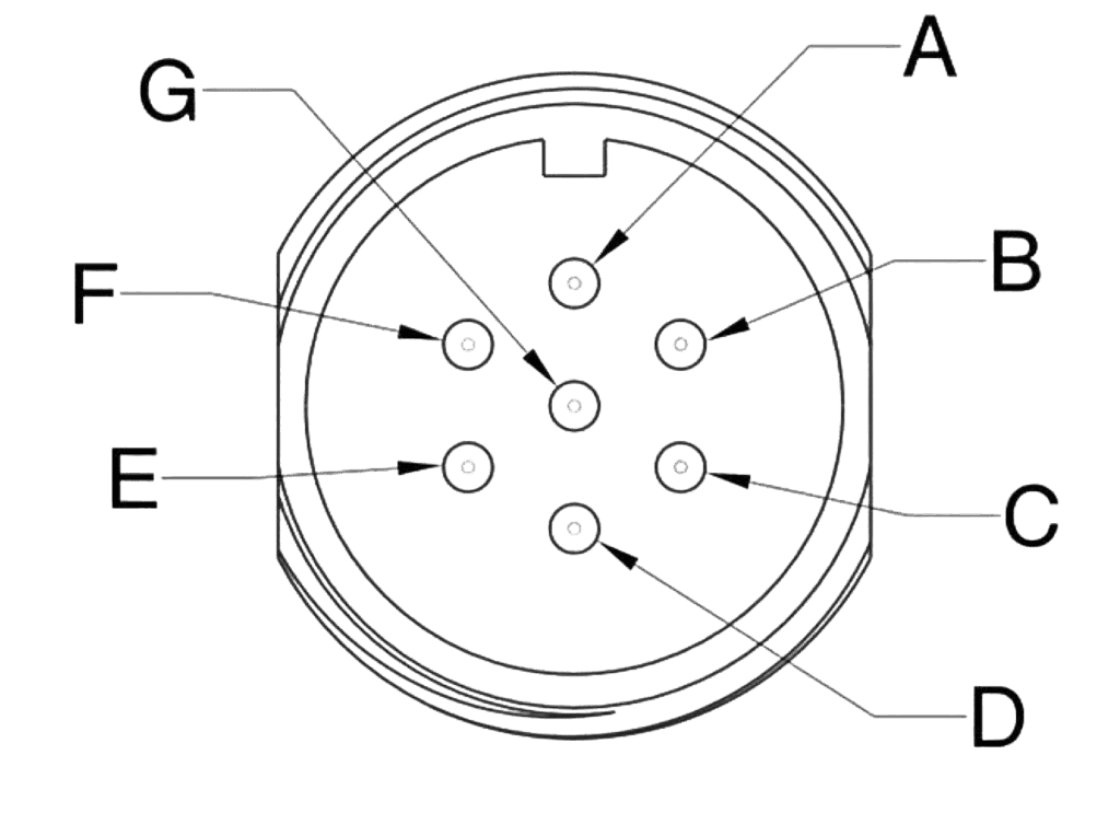
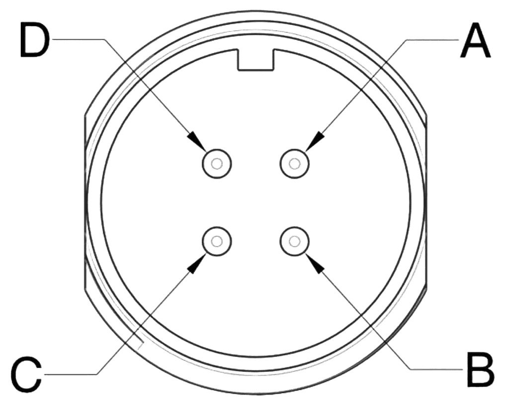
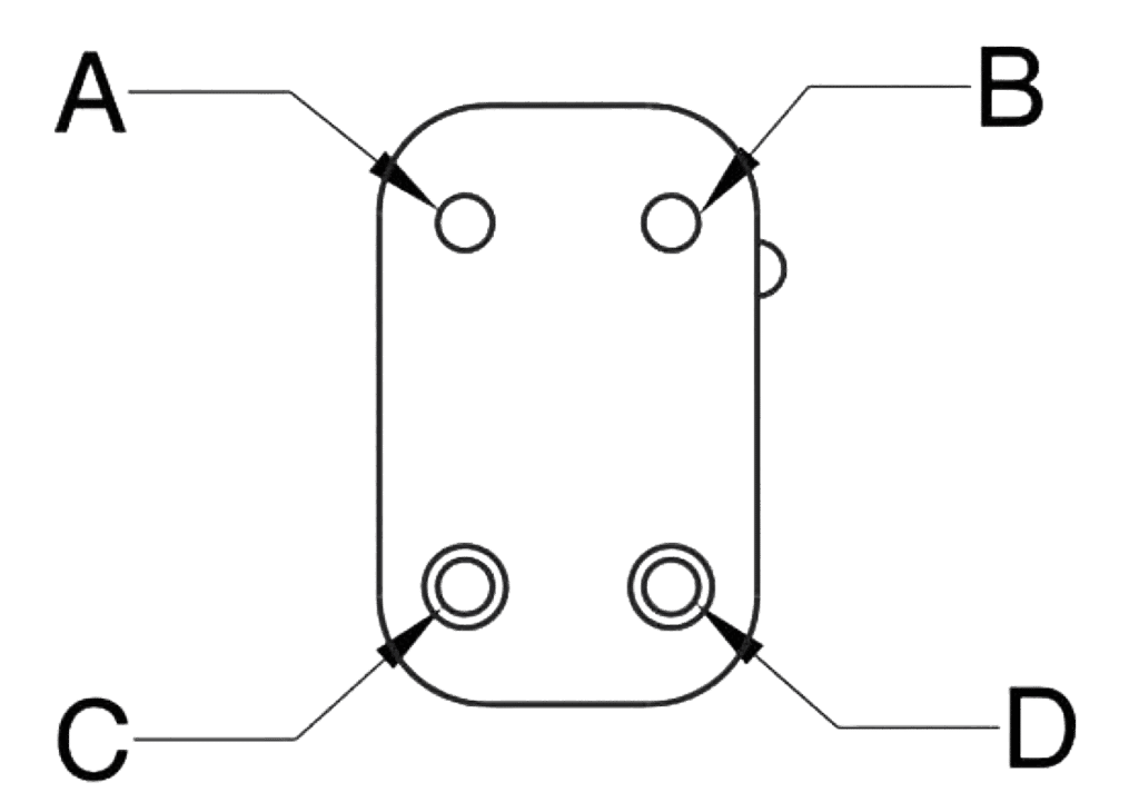
Please note pin orientation. Not to scale. Flying leads that terminate in bare wires do not have associated diagrams. In these cases, please refer to the wire color to determinate the correct pin out.
Type: Flying Lead (300 mm length)
Termination: Bare Wires
Wire Color 11185_d94739-09> |
Function 11185_de5166-c5> |
Desc. 11185_33ef58-2f> |
White 11185_e7b674-3d> |
Supply 0 V 11185_978a89-e8> |
0 V 11185_3d9dcb-d6> |
Black 11185_61be3a-5a> |
Supply + 11185_3ee0cb-05> |
+24 V 11185_c3964c-8f> |
Green 11185_86d3d6-cc> |
Input – (Ground Ref) 11185_f33d1a-94> |
Differential Input Signal, – 11185_ffc420-c2> |
Red 11185_78702c-86> |
Input + 11185_8d70df-b9> |
Differential Input Signal, + 11185_9aadff-a7> |
Type: Case Mounted
Termination: Connector according to EN 175201-804/MIL 5015 equivalent, shell size 14
Pin 11185_30cc30-7d> |
Function 11185_34fd98-1e> |
Desc. 11185_9eef65-70> |
A 11185_c62ba7-cc> |
Supply + 11185_7461cb-fd> |
+24 V 11185_e66d10-83> |
B 11185_1c2ef6-f7> |
Supply 0 V 11185_1d4698-23> |
0 V 11185_1fa4ff-e1> |
C 11185_774e53-8b> |
Output – |
Output 0 V Reference |
D 11185_f7805d-43> |
Input + 11185_1eff54-51> |
Differential Input, + 11185_ebd23a-a2> |
E 11185_36a4a0-85> |
Input – 11185_319162-ef> |
Differential Input, – 11185_f4994f-64> |
F 11185_8b4137-8f> |
Output + 11185_47a07b-1d> |
Output Signal 11185_9d49d9-ea> |
G 11185_5a1bb3-f5> |
Earth 11185_a00c1a-98> |
– 11185_cb44b0-4b> |
* When the enable function is selected, the function of pin C is the enable input. This replaces the standard pin function.
Type: Case Mounted
Termination: Connector according to EN 175201-804/MIL 5015 equivalent, shell size 14
Number of Contacts: 4
Pin 11185_78a553-34> |
Function 11185_59fc05-c8> |
Desc. 11185_d6baac-02> |
A 11185_126b5b-9a> |
Supply + 11185_67ff98-99> |
+24 V 11185_ca5440-96> |
B 11185_07300e-4e> |
Input + 11185_0df0d6-4a> |
Differential Input, + 11185_23c981-64> |
C 11185_b3e0b1-d5> |
Input – 11185_6dfde6-69> |
Differential Input, – 11185_5ef215-1f> |
D 11185_8b511d-cb> |
Supply 0 V 11185_cc6f30-ce> |
0 V 11185_3cd227-50> |
Type: Flying Lead
Termination: Winchester™ G4-20P
Pin 11185_dd4382-cd> |
Function 11185_5b5215-58> |
Desc. 11185_b46509-db> |
A 11185_4bd862-ae> |
Supply 0 v 11185_74e5c6-fa> |
0 v 11185_a9096b-c3> |
B 11185_896c34-52> |
Supply + 11185_eb4144-90> |
+24 V 11185_57d0e8-c3> |
C 11185_165bae-e3> |
Input – (Ground Ref) 11185_7a7796-f6> |
Differential Input, – 11185_bcf1f1-83> |
D 11185_600333-55> |
Input + 11185_ca4af3-6c> |
Differential Input, + 11185_ad0fe6-73> |
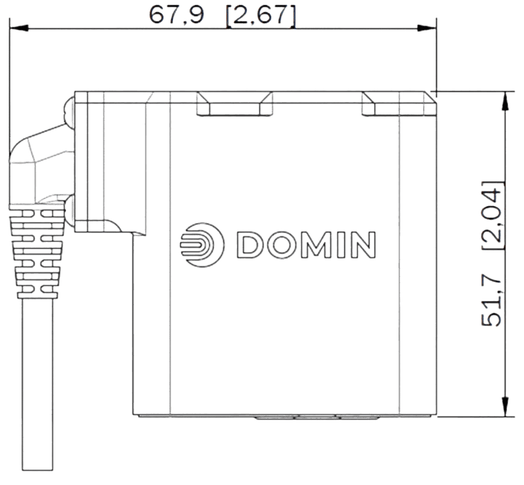
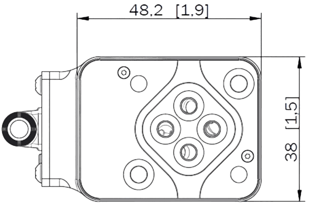
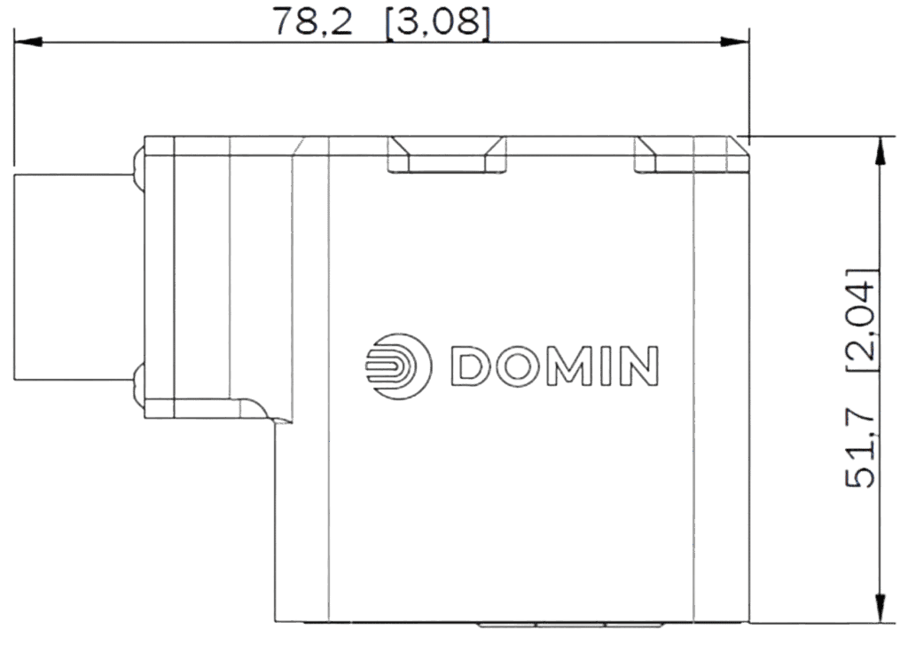
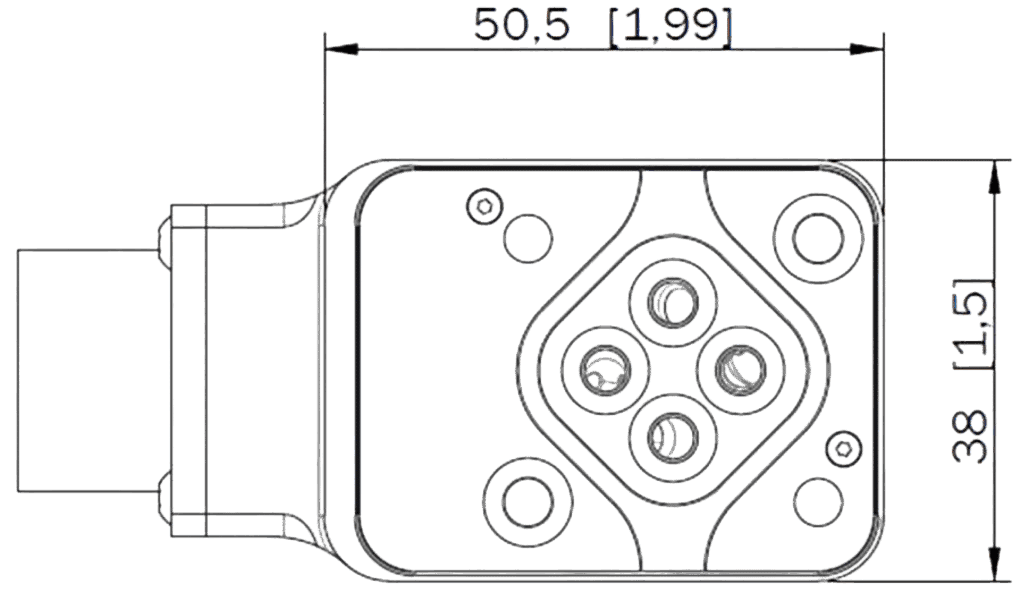
Unit Dimensions – Connector Code G and B4
Unit Dimensions – Connector Code E and E4
Nominal dimensions are displayed in mm. Bracketed dimensions are in inches. Not to scale.
Mounting Surface Pattern Dimensions
11185_d4230d-c6> |
Dia Ø |
X Position |
Y Position |
F1 11185_daed33-32> |
M4 11185_a12327-9c> |
0 11185_6ef4ab-8c> |
0 11185_8d436f-4f> |
F2 11185_9cb86c-97> |
M4 11185_03fb01-b9> |
23.8 11185_f8a43c-32> |
0 11185_7cfdef-63> |
F3 11185_de34f5-18> |
M4 11185_c33fa5-64> |
23.8 11185_07fafe-63> |
26.2 11185_885c01-7f> |
F4 11185_e6ef15-5a> |
M4 11185_9d5153-99> |
0 11185_4f6b61-b5> |
26.2 11185_750314-d6> |
P 11185_ab125c-90> |
3.8 11185_6c1756-b9> |
11.9 11185_8212e9-bb> |
19.2 11185_d8216e-0e> |
A 11185_745426-60> |
3.8 11185_3c1869-5a> |
18.0 11185_76fd34-b9> |
13.1 11185_387fef-b3> |
B 11185_20db00-8b> |
3.8 11185_b3231a-3d> |
5.8 11185_357f19-75> |
13.1 11185_2a4987-5a> |
T 11185_a024c8-72> |
3.8 11185_e883e6-ff> |
11.9 11185_14011a-57> |
7.0 11185_cc81ef-c2> |
Bolts (F1, F2, F3, F4)
Type: M4 x 55 DIN EN ISO 4762-10.9
Required Torque: 2.5 Nm (1.8 ft-lbf)
O-Rings (P, A, B, T)
Type: 4.47 x Ø 1.78 (ISO 3601-1-008)
Material: NBR, EPDM or Viton, 70 Shore A
Hardness: 70 Shore A
Standards Compliance
EMC Regulations: EN 61000-6-2 / EN55011:1998+A1
Performance Tests: ISO 10770-1
Pressure Rating: EN 10771
Hydraulic Interface: ISO 10372-01-01-0-92
Not to scale.
Ordering Code
S4 Pro 1 2 3 4 5 6 7 8 9
Any value in range 0.5 to 18 11185_095af6-dd> |
Rate flow in l/min for 35 bar ∆P per control edge 11185_009f4c-d0> |
R – Suffix for reversal of A and B port e.g. 18R 11185_8290e7-32> |
A 11185_b7fa3e-b2> |
Axis cut (1% overlap linearized) 11185_a80ebe-33> |
O 11185_9adbe0-0b> |
3% Overlap (linearized to 50% gain over center) 11185_a57caa-9c> |
D 11185_2017d4-7d> |
10% Overlap (with flow dead band) 11185_63827e-b7> |
X 11185_63efab-9a> |
For other options please enquire 11185_470a94-9e> |
A 11185_4574cc-64> |
± 10 V 11185_3a8646-0d> |
B 11185_284a33-4e> |
± 20 mA 11185_c97eb5-f5> |
C 11185_3a8d34-bc> |
4 to 20 mA 11185_526116-b0> |
D 11185_957162-b2> |
± 5 V 11185_3a0dc6-30> |
X 11185_99a6ae-b7> |
For other options please enquire 11185_84c73f-55> |
11185_8e7642-03> |
For differing input and output signals, use two letters, |
C 11185_d3114d-76> |
Center 11185_f10f4f-46> |
X 11185_a34107-2d> |
For other options please enquire 11185_875322-40> |
E 11185_8c300b-35> |
6 pin + PE circular connector* 11185_3b4cd2-cf> |
E4 11185_276da7-a3> |
4 pin circular connector* 11185_0c57f3-41> |
B4 11185_d40935-c3> |
4 contact, unterminated flying lead 11185_ca91fb-6a> |
G 11185_9f69f2-16> |
G4-20P Rack and Panel connector 11185_81b88c-19> |
X 11185_095221-b7> |
For other options please enquire 11185_9af164-96> |
* EN 175201-804/MIL 5015 equivalent connector, shell size 14
Y 11185_af8488-87> |
Enable mode on (Only available with connector option E) 11185_8f5cd2-ff> |
N 11185_85cb9f-a0> |
No enable functionality 11185_093c51-63> |
R 11185_36a1d7-4d> |
Recommended – any hydraulic oil in accordance with DIN 51524, filtered in accordance with ISO4406 18/16/13. Compatibility with water-free synthetic fluids available on enquiry. 11185_64b878-59> |
X 11185_5337ae-3e> |
For other options please enquire 11185_ff12f8-15> |
N 11185_4cb640-6e> |
Nitrile 11185_df33a1-20> |
V 11185_04802b-e0> |
Viton 11185_489fdd-d5> |
X 11185_bd4e32-48> |
For other options please enquire 11185_8ed88c-c7> |
Assigned individually to any with customized options upon enquiry 11185_3751e5-24> |
Variants on Request
Domin is proud of their ability to offer tailored solutions that meet customers’ specific needs. If you require a non-standard configuration, or a bespoke modification, we are confident we can provide you with the best solution. Talk to us here and one of our team will respond as soon as possible.
Domin is a supplier and servo valve manufacturer for various applications including automotive/motorsports, aerospace, animatronics, simulation, robotics, and marine.