
Flow Divider Insights and Tips
September 16, 2025
Flow Divider Applications
Tips to Optimize Flow Divider Performance
Choosing a Flow Divider Model
Flow Divider Applications
In hydraulic systems, flow dividers split flow into precise, proportional sections from a single pump. This ensures multiple cylinders or actuators operate in perfect synchronization. These devices are most common in lifting applications, where they help keep platforms and stages level. Beyond lifting, flow dividers provide consistent actuation of cylinders to help operate gates and doors. In certain circuit designs, flow dividers can even serve as pressure intensifiers, boosting force in one branch without the cost or complexity of an additional pump.
Lifting Platforms and Stages
In multi-cylinder lifting systems, even slight actuator misalignment can lead to side loading, uneven wear, or instability. Reliable lifting requires more than force. It calls for controlled synchronization.
Flow dividers ensure this by keeping all cylinders in sync regardless of pressure fluctuations or load variations. In a four-cylinder scissor lift, the flow divider keeps all cylinders balanced, preventing drift, binding, or skewing while minimizing stress on both the cylinders and the supporting structure.
Typical Applications
Common lifting applications include the following:
Actuating and Positioning Components
Aside from synchronizing cylinders for lifting applications, flow dividers help regulate and coordinate repeated movements for entry points and attachments. In paper mills, they synchronize cylinders that adjust and pivot conveyors, ensuring heavy paper rolls are positioned correctly to be processed.
Typical Applications
Common actuation and position applications include the following:
Intensifying Pressure
Beyond synchronization capabilities, flow dividers can be used to multiply pressure for press and clamping applications. Here, pressure is intensified by combining high flow fluid from the sections of the divider. From there, the outputs are discarded to tank, which increases the pressure in the circuit.
This type of hydraulic circuit can be employed where a low-pressure circuit is already in use and where there is only need of small high-pressure flow. Since flow dividers offer a minimal loss of internal pressure at a low cost, this is an effective solution.
Typical Applications
Common intensification applications include the following:
3 Tips to Optimize Flow Divider Performance
1. Install close to cylinders
The location of flow dividers in relation to the cylinders plays a key role in performance. For improved accuracy, install the flow divider as near to the cylinders as possible.
2. Keep hydraulic lines uniform
Ensuring that hydraulic lines to each cylinder are similar in length will further help maintain balance and consistency.
3. Operate near maximum flow rate
Accuracy is generally better when operating closer to the divider’s maximum flow rate. As a guideline, the expected flow should ideally remain above the midpoint of the flow range.
Bottom Line:
For optimal performance, place the divider near the cylinders, use equal-length lines, and run above the flow midpoint (ex: operate at 5 gpm or higher for a given range of 1–9 gpm).
Choosing a Flow Divider Model
Our range includes four flow divider types. Gear flow dividers cover 95% of our customer applications, while radial piston and volumetric dividers are engineered for situations where the application leaves no room for error. Flow divider valves can be installed when a wider margin of error is acceptable.
Flow Divider Valves (Low-Range Accuracy)
When precision is secondary to affordability, flow divider valves can be used. These two-section dividers are designed for compact applications with synchronization errors between ±4 to 5%.
Two models are available, both with identical flow capacity. The difference lies in their housing material and pressure ratings.
MKA (Aluminum) and MKS (Steel)
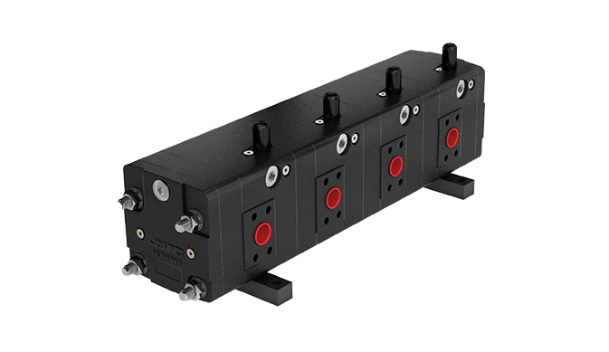
Gear Flow Dividers (Standard Accuracy)
Gear flow dividers remain the most commonly used design, offering standard synchronization errors within ±1.5 to 4%. When comparing models, key factors to consider include the flow capacity, material, and porting style.
All three models can be built up to 12 sections. The MTO is offered in two materials, lightweight aluminum for small flow rates or cast iron for high flow rates. When even greater flow is required, the cast iron HTO is the best fit. It is designed with an integrated port layout to save installation space.
MTO (Aluminum), most popular model
MTO (Cast Iron)
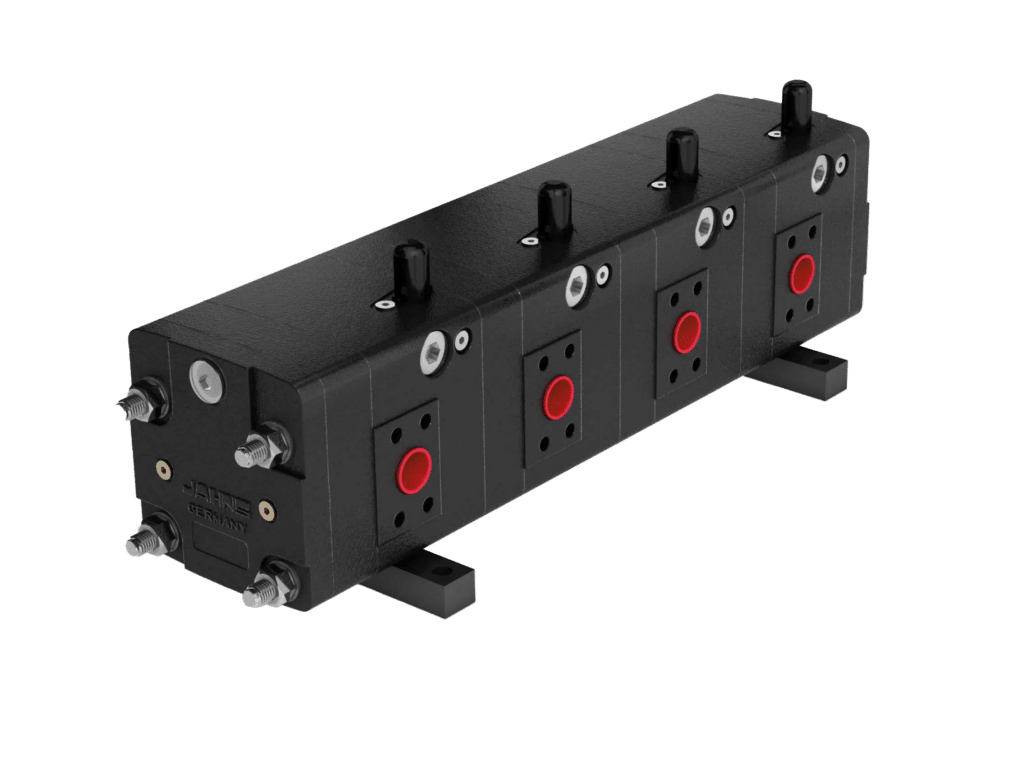
HTO (Cast Iron)
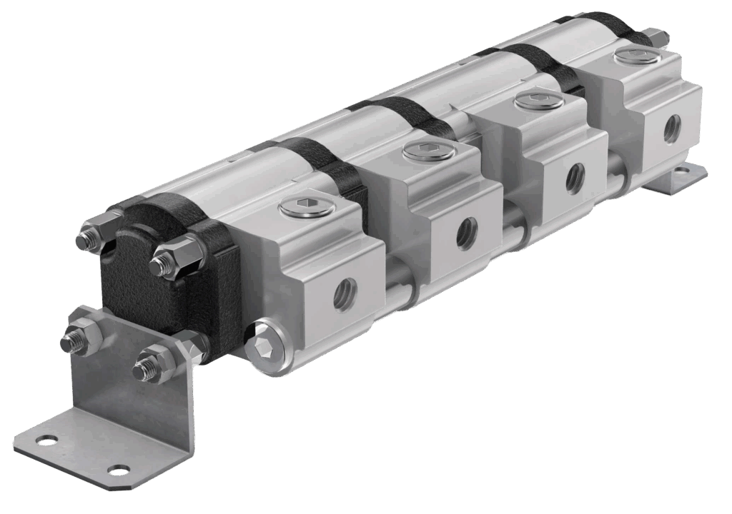
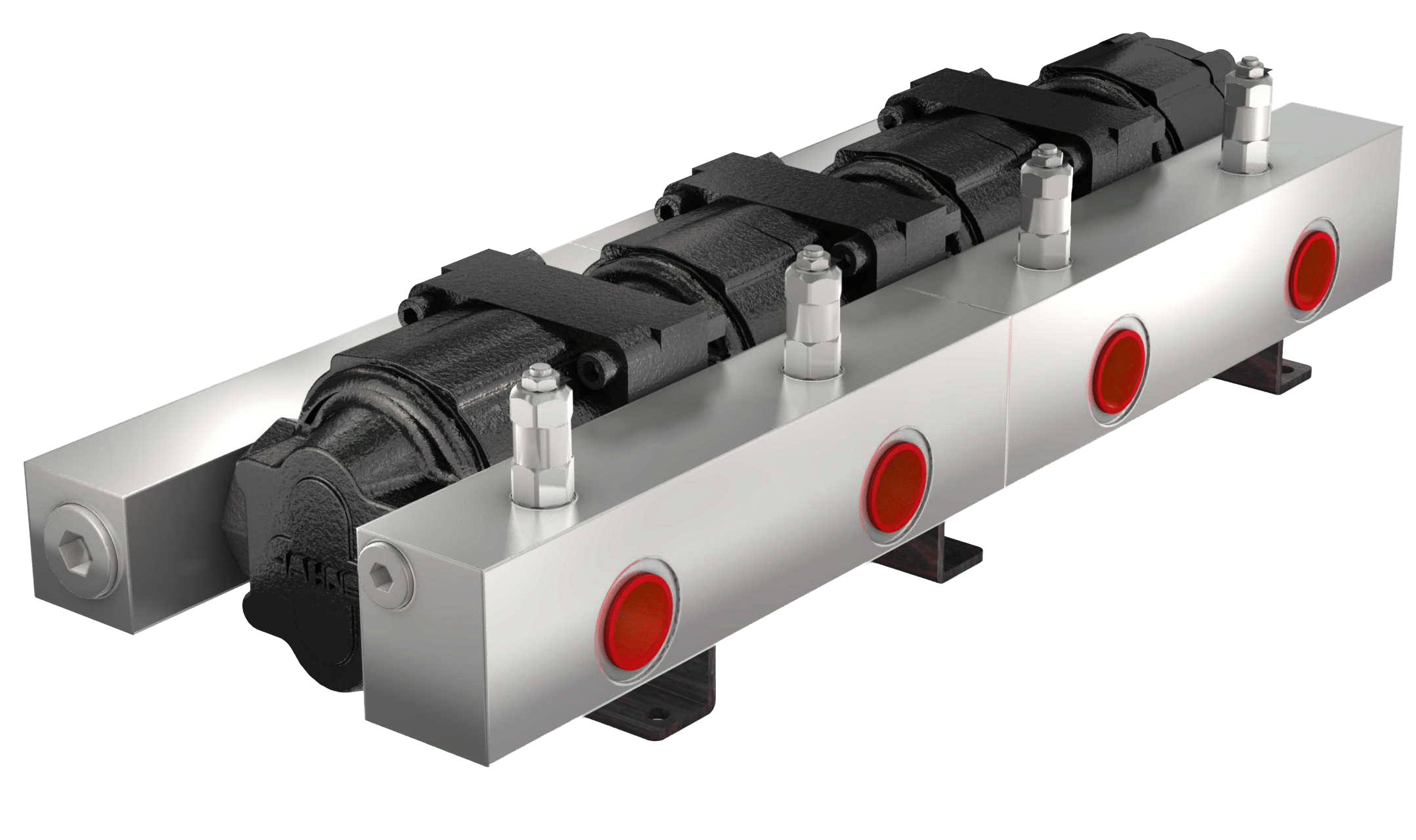
Radial Piston Flow Dividers (Mid-Range Accuracy)
Radial piston dividers offer tighter synchronization errors between ±0.5 to 0.8%. Engineers should account for higher pressure drops, which are inherent to the design.
There are three radial piston models, all constructed from steel. The most popular model is the MT-GM, which is a two-section divider, that is ideal for applications requiring a small footprint. For larger systems, The MTL and STL series offer up to 12 sections.
The STL model is chosen when a higher flow rate is needed. The smallest STL size has almost double the displacement (per section) of the largest MTL model, making it the go-to choice when maximum throughput and efficiency are critical.

MT-GM, most popular model

MTL
STL
Volumetric Flow Dividers (Near-Perfect Accuracy)
Volumetric flow dividers operate as close to 100% accuracy as hydraulics allows. Any volume error due to machining will therefore be negligible and almost impossible to measure.
There are two main designs: MZB and MLH. Unlike other flow dividers, volumetric dividers work by precisely transferring measured volumes between a master synchronizer and the working cylinders. Both designs offer similar accuracy, with the primary difference being their cylinder configuration.
The MLH linear stroke divider offers 3 to 8 sections with cylinders that are arranged around a master cylinder. In the MZB, multiple cylinders are configured in-line with the pistons sequentially attached to one continuous piston rod. The number of chambers equates to the number of cylinders that are required to operate. For example, a 12-cylinder configuration would require a 12 chamber divider.
