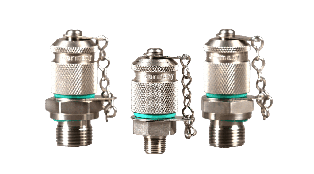
Pressure is one of the most important diagnostic parameters in the hydraulic circuit. Obtaining pressure readings is essential to successful preventive maintenance and troubleshooting. The Spradow test points allow the connection of a pressure gauge in only seconds while the equipment is running. It is the safest, cleanest and most convenient way of measuring pressure. Designing your equipment with the Spradow test points will improve the quality of your equipment and in today’s market, higher quality makes the equipment more attractive to potential buyers. The spring loaded check valve inside the test point opens during engagement of the special micro-bore hose fitting end. The connection can be performed under pressure without the use of tools. A single gauge connected to the high pressure micro-bore hose can check an unlimited number of test points. We also offer various types of hose assemblies for direct connection to the test fitting.
Material Data:
Max working pressure
9,135 psi (629 bar)
Temperature range
-4ºF to 322ºF (-15ºC to 161ºC)
Threads
M16 x 2
Metal material
Carbon steel and zinc chromate (stainless steel available upon request)
Seal options
NBR, 90 durometer (others by request)
ISO Standard
DIN ISO 4042
Compatibility
Interchangeable with other brands
Spradow is a supplier and test point and test hose assembly manufacturer for various applications including construction, mechanical, technological, and industrial.
Test Points and Test Hose Assemblies Pressure is one of the most important diagnostic parameters in the hydraulic circuit. Obtaining… Read More »Test Points & Test Hose Specs
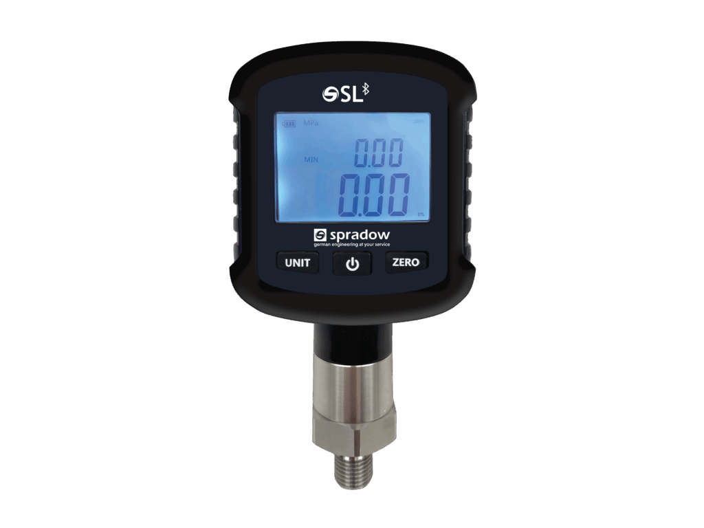
Smart Logger Pressure Gauge Smart Logger Bluetooth digital pressure gauges incorporate a high precision pressure sensor with an accurate LCD… Read More »Smart Logger Pressure Gauge
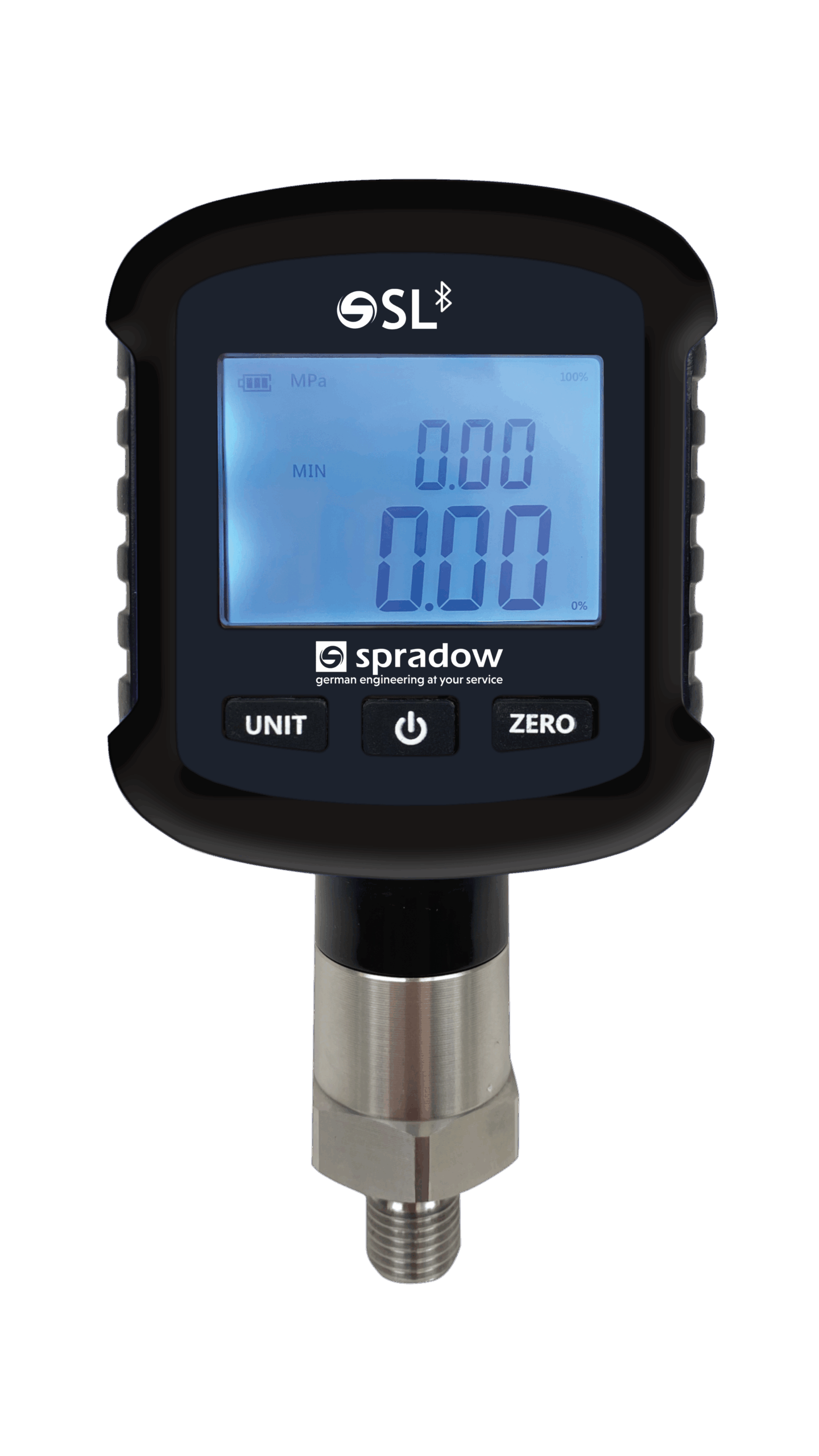
Smart Logger Bluetooth digital pressure gauges incorporate a high precision pressure sensor with an accurate LCD display showing measured pressure in real time and can transmit readings up to 10 Hz via Bluetooth.
This digital pressure gauge is equipped with a large size LCD liquid crystal display, which has multiple functions such as zero reset, backlight, power on and off, pressure unit selection & low voltage alarms. Easy to operate and install, the display can be rotated 330° which is convenient for operators to read from different angles. The unit is supplied with a protective rubber shroud has good shock resistance and can measure gas, liquid, oil and other media that are not corrosive to stainless steel. This Smart Logger Bluetooth digital pressure gauge supports iOS and Android Bluetooth apps with configuration parameters that include display of pressure values, acquisition rate modification, zero reset operation and start/stop logging.
Smart Logger Bluetooth digital pressure gauges are suitable for portable pressure measurement, equipment matching, calibration equipment and other pressure measurement fields.
Advantages at a Glance:
Dial can be rotated 330º
Easy operation
Multiple selectable pressure units
Zero reset and backlight
Bluetooth connection to iOS and Android apps with datalogging
Low power consumption design, 2x AA batteries
12 months of battery life
Ergonomic & robust design, with rubber shroud and easy operation
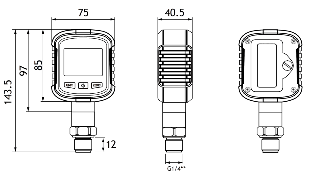
Other dimensions on request. We reserve the right to change the technical performance. All dimensions in mm. ± 0.5 mm.
*G1/4″ WD Flat sealing, other threads available on request.
Spradow is a supplier and test point and test hose assembly manufacturer for various applications including construction, mechanical, technological, and industrial.
Test Points and Test Hose Assemblies Pressure is one of the most important diagnostic parameters in the hydraulic circuit. Obtaining… Read More »Test Points & Test Hose Specs
Smart Logger Pressure Gauge Smart Logger Bluetooth digital pressure gauges incorporate a high precision pressure sensor with an accurate LCD… Read More »Smart Logger Pressure Gauge
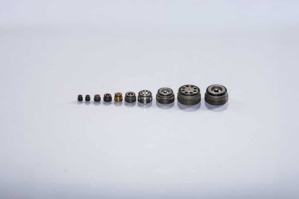
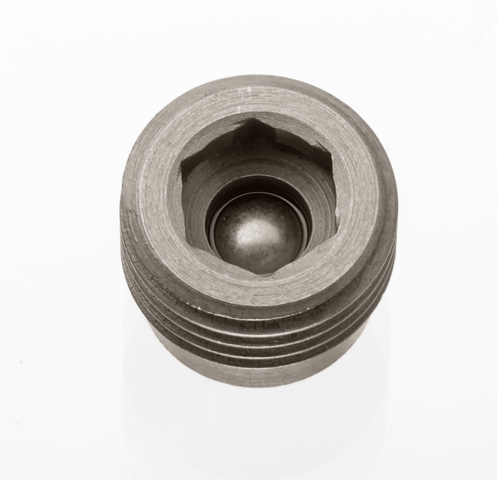
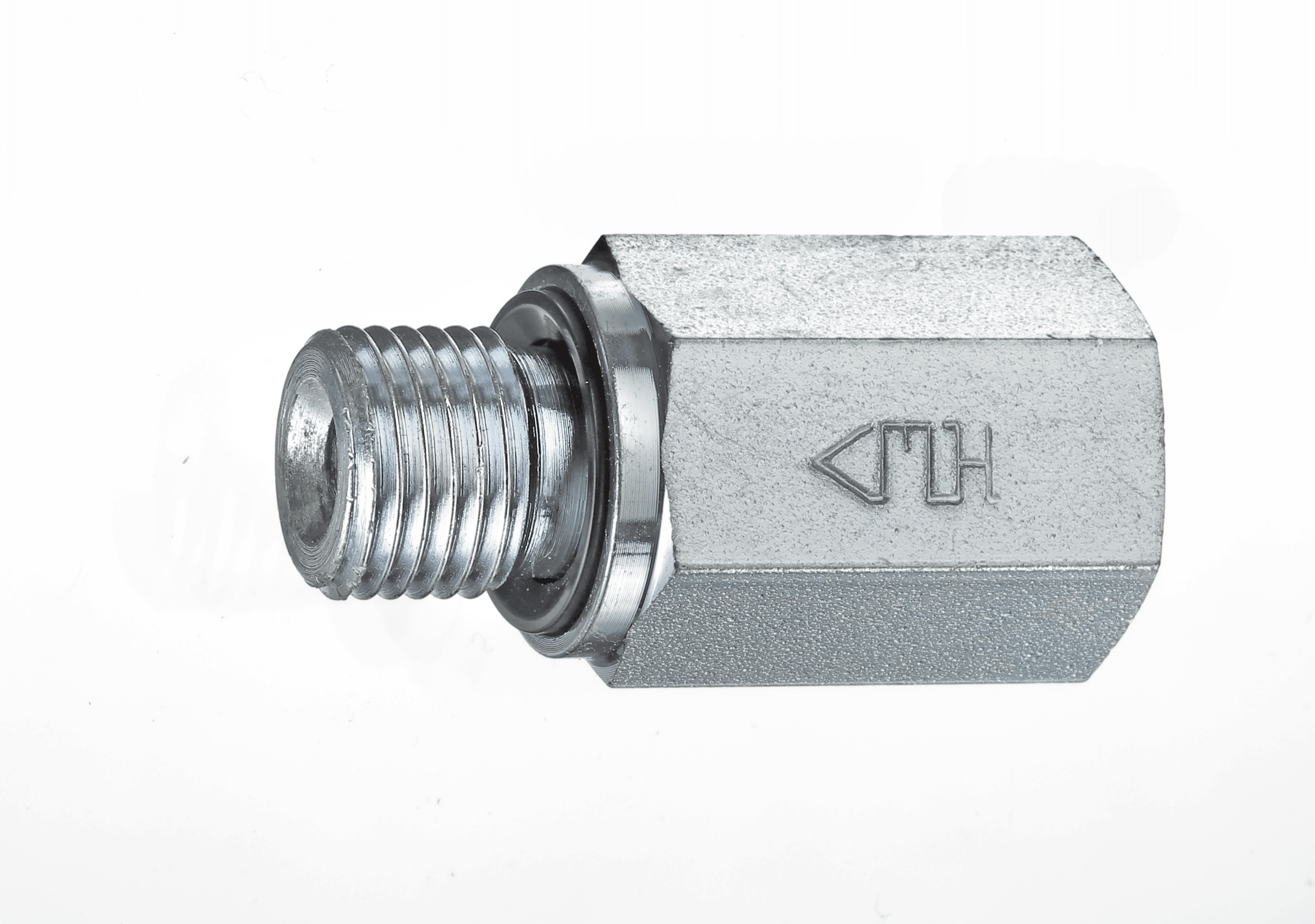
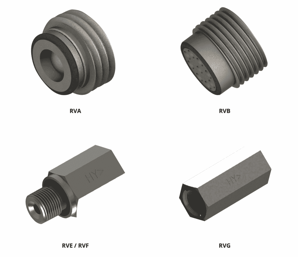
Check valves block an oil flow in one direction and allow it in the other direction. They are a type of shutoff valve. The check valve is inserted when an oil flow shall be allowed in one direction only. Meanwhile, the usage of check valves prevents backflow of the fluid.
Advantages at a Glance:
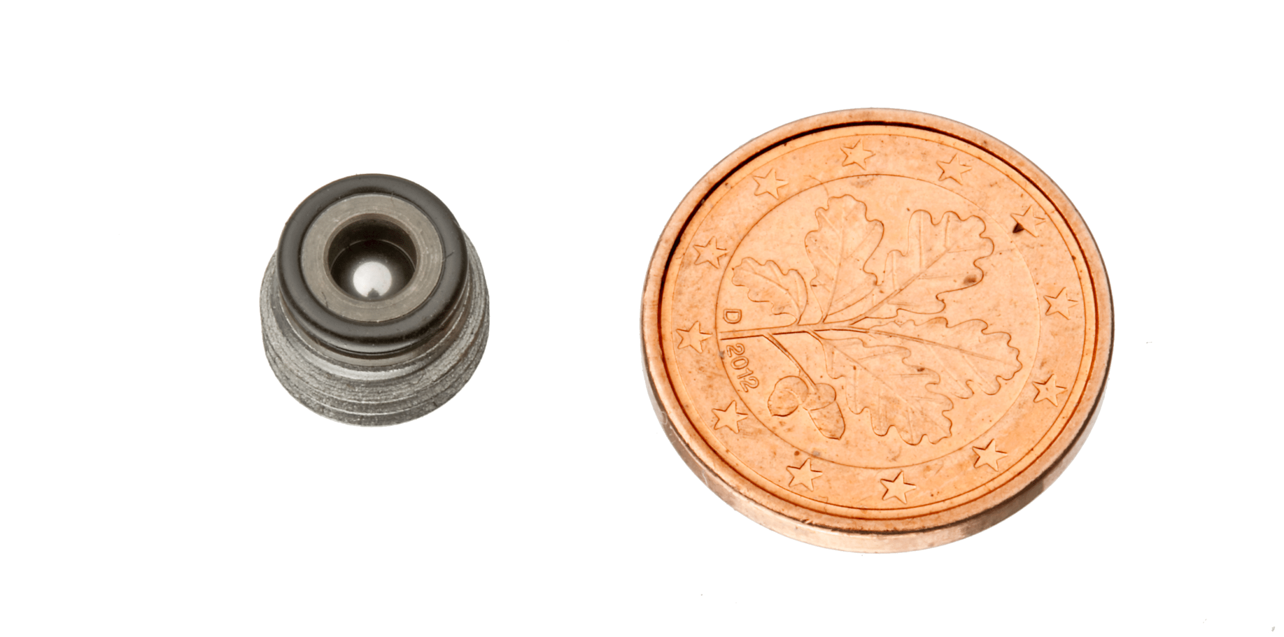
Spherical shell
Available as screw-in or caged version
Nominal size 1/16 – 1/8 – 1/4 – 3/8 – 1/2 – 3/4
Working pressure 10,000 psi
BSP or metric thread
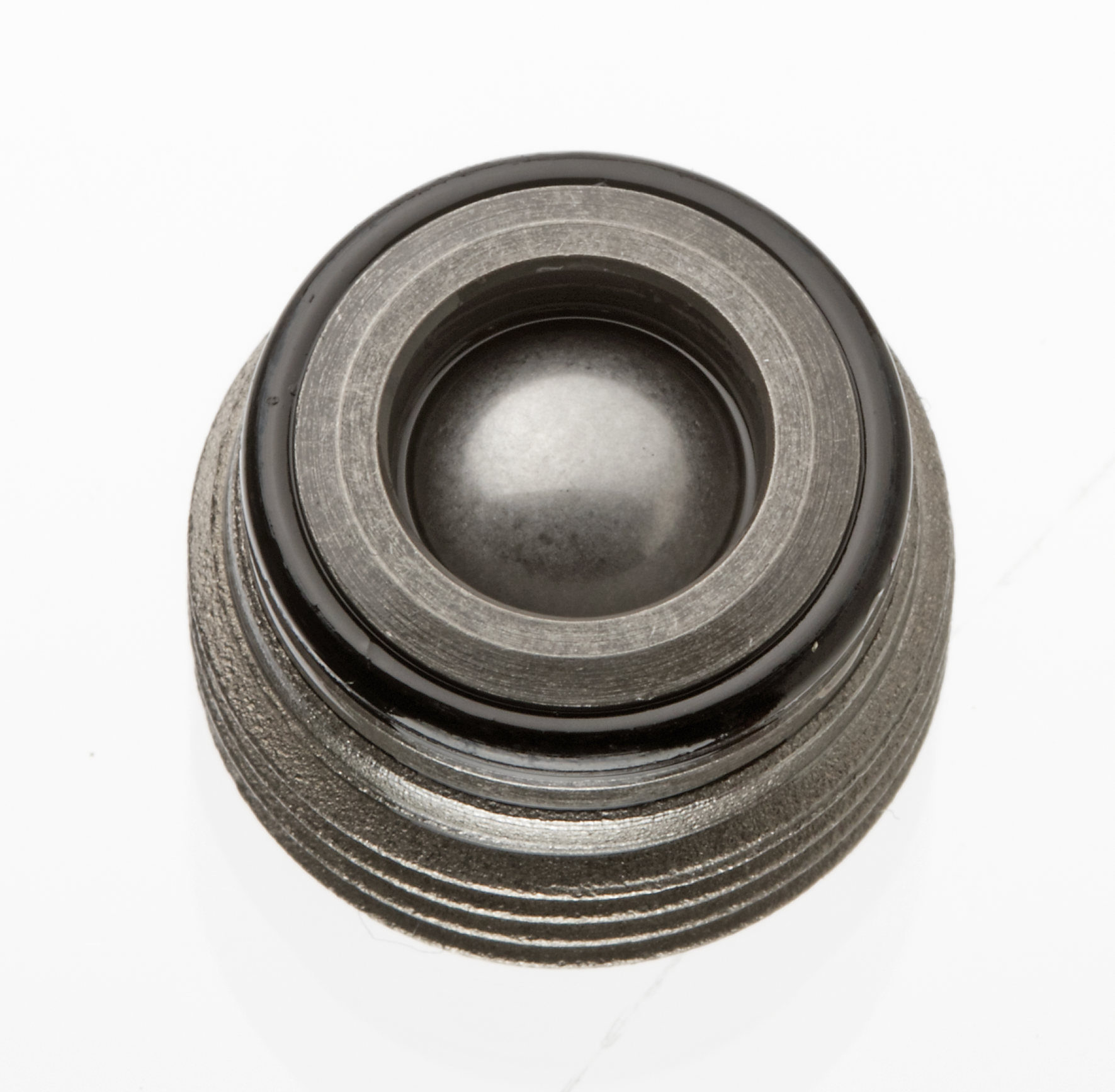
The HYTORC-check valves are available with a screw-in or caged design. Even so, both designs can be obtained in two flow directions: with the screw-in direction closed or with free-flow. The spherical cap remains reliably tight in every position, in case of multiple switching cycles and under severe stress.
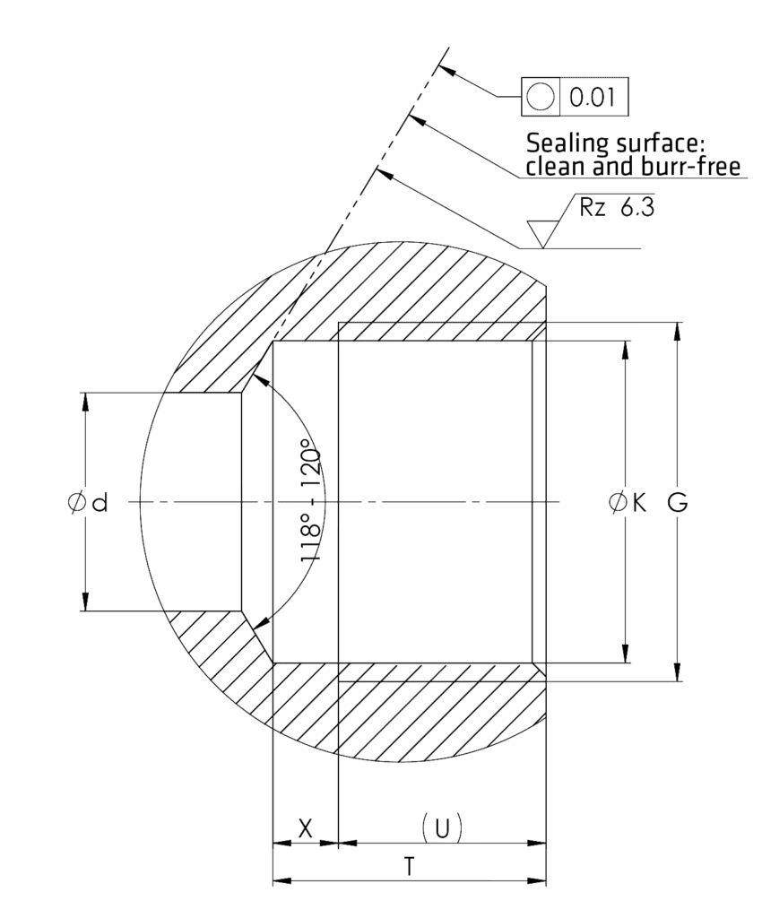
The HYTORC check valve easily screws into a regular hole (Dimensions screw-in drill). The screw-in check valves are sealed through an edge sealing which is turned to the cage. The edge sealing, together with the drill draft, forms a gap-free chamber for the O-Ring. The gap-free chamber and the O-Ring are repeatable sealing.
The valve is made of a high-strength hardened steel. Moreover, the ball seat is specially treated and the spherical shell is manufactured with a high tensile hardened and polished ball bearing ball. Thus, the design of the check valves is compact and economical which saves space and offers simple installation.
Use the widget tool below to find the right check valve type for your application.
Check Valve Type Selector Widget
Then refer to the drop down menus to find the technical information for your desired check valve model.
Technical Data
Permissible Operating Pressure
up to 10,000 psi (700 bar) (lock pressure)
Permissible Temperature
–40 to +176 °F (–40º +80°C)
Viscosity
5–500 cSt
Installation Position
any
Material
Body: normal and stainless Steel Gasket: NBR rubber
Screw-In Check Valve
Order No.
Type
G
L
a
n
z x d
o-ring
12 011 102
RVA 2-M
M 6
6
3.4
3.4
4 x 1.2
2.5 x 1
12 011 103
RVA 3-M
M 8×1
6
3.3
4.7
6 x 1.6
4 x 1
12 011 104
RVA 4 (RVA 4-M)
G 1/8 M 10×1
6.7
3.5
6
6 x 1.8
6 x 1
12 011 106
RVA 6 (RVA 6-M)
G 1/4 M 14×1.5
8.2
4.8
8.9
8 x 2.15
9 x 1
12 011 108
RVA 8 (RVA 8-M)
G 3/8 M 18×1.5
10.1
5.6
10.8
8 x 3.2
11 x 1.5
12 011 110
RVA 10 (RVA 10-M)
G 1/2 M 22×1.5
11.6
6.8
14 (14.5)
8 x 3.8
14 x 1.5
12 011 116
RVA 16 (RVA 16-M)
G 3/4 M 27×2
14.2
7.8
18.5
8 x 4.6
18.77 x 1.78
Screw-In Drill
Type
G
K
d [max]
T [min]
U
X [max]
RVA 2-M
M 6
5H11
2
6
4.2
1.8
RVA 3-M
M 8×1
7H11
3.5
5.9
4.1
1.8
RVA 4 (RVA 4-M)
G 1/8 M 10×1
8.8H11 (9H11)
5
6.5
4.3
2.2
RVA 6 (RVA 6-M)
G 1/4 M 14×1.5
11.8H11 (12.5H11)
8
8
5.8
2.2
RVA 8 (RVA 8-M)
G 3/8 M 18×1.5
15.25H11 (16.5H11)
10
9.3
6.7
2.6
RVA 10 (RVA 10-M)
G 1/2 M 22×1.5
19H11 (20.5H11)
12
10.5
8
2.5
RVA 16 (RVA 16-M)
G 3/4 M 27×2
24.5H11 (25H11)
16
13
8.7
4.3
RVA Opening Pressure + Starting Torque
NG
2
3
4
6
8
10
16
Opening Pressure
bar
0.36
0.26
0.17
0.19
0.22
0.18
0.17
Starting Torque
Nm
6
8
12
20
25
40
80
Screw-In Check Valve
Order No.
Type
G
L
a
AF
o-ring
12 011 202
RVB 2-M
M 6
6.3
3.3
3
2.5 x 1
12 011 203
RVB 3-M
M 8×1
6.6
3.6
4
4 x 1
12 011 204
RVB 4 (RVB 4-M)
G 1/8 M 10×1
7.7
4.6
5
6 x 1
12 011 206
RVB 6 (RVB 6-M)
G 1/4 M 14×1.5
10
6.6
7
9 x 1
12 011 208
RVB 8 (RVB 8-M)
G 3/8 M 18×1.5
11.4
7.5
8
11 x 1.5
12 011 210
RVB 10 (RVB 10-M)
G 1/2 M 22×1.5
13.1
8
10
14 x 1.5
12 011 216
RVB 16 (RVB 16-M)
G 3/4 M 27×2
16.9
10.7
12
18.77 x 1.78
Screw-In Drill
Type
G
K
d [max]
T [min]
U
X [max]
RVA 2-M
M 6
5H11
2
6.7
4.2
2.2
RVA 3-M
M 8×1
7H11
3.5
6.5
4.4
2.1
RVA 4 (RVA 4-M)
G 1/8 M 10×1
8.8H11 (9H11)
5
7.5
5.3
2.2
RVA 6 (RVA 6-M)
G 1/4 M 14×1.5
11.8H11 (12.5H11)
8
10
7.6
2.4
RVA 8 (RVA 8-M)
G 3/8 M 18×1.5
15.25H11 (16.5H11)
10
10.9
8.6
2.3
RVA 10 (RVA 10-M)
G 1/2 M 22×1.5
19H11 (20.5H11)
12
12
9.1
2.9
RVA 16 (RVA 16-M)
G 3/4 M 27×2
24.5H11 (25H11)
16
15.5
11.5
4
RVB Opening Pressure and Starting Torque
NG
2
3
4
6
8
10
16
Opening Pressure
bar
0.77
0.47
0.22
0.22
0.2
0.23
0.2
Starting Torque
Nm
6
8
12
20
25
40
80
RVE Screw-In Socket with Elastic Sealing
Order No.
Type
G
L
t
O
AF
12 011 306
RVE 6
G 1/4
40
12
2.5
19
12 011 308
RVE 8
G 3/8
42
12
2.5
22
12 011 310
RVE 10
G 1/2
51
14
3
27
RVF Screw-In Socket with Elastic Sealing
Order No.
Type
G
L
t
O
AF
12 011 406
RVF 6
G 1/4
40
12
2.5
19
12 011 408
RVF 8
G 3/8
42
12
2.5
22
12 011 410
RVF 10
G 1/2
51
14
3
27
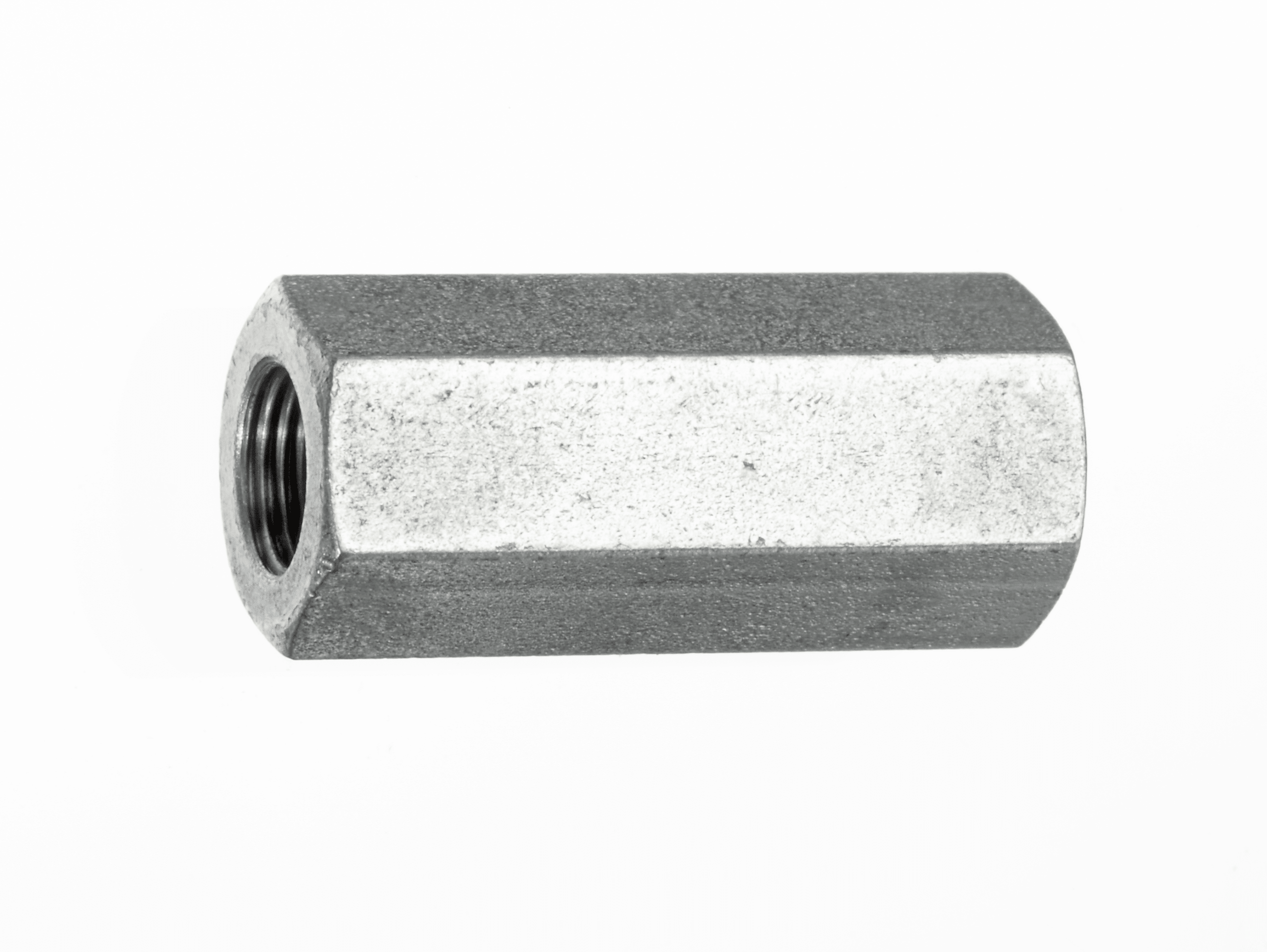
RVG Internal Thread on Both Sides
Order No.
Type
G
L
t
AF
12 011 506
RVG 6
G 1/4
45
12
19
12 011 508
RVG 8
G 3/8
48
12
22
12 011 510
RVG 10
G 1/2
58
14
27
RVA, RVE, RVG Flow Rate
Curve
Q Max l/min
1
=RVA2
3
2
=RVA3
6
3
=RVA4 – RVE4 – RVG4
10
4
=RVA6 – RVE6 – RVG6
25
5
=RVA8 – RVE8 – RVG8
45
6
=RVA10 – RVE10 – RVG10
70
7
=RVA16 – RVE16 – RVG16
100
RVB, RVF Flow Rate
Curve
Q Max l/min
8
=RVB2
2
9
=RVB3
4
10
=RVB4 – RVF4
8
11
=RVB6 – RVF6
18
12
=RVB8 – RVF8
30
13
=RVB10 – RVF10
60
14
=RVB16 – RVF16
90
Fitting Tools
Order No.
Desc.
for Type
b
zxd
c max
AF
9 05855 00
RMS 2
RVA 2
3.3
4×1
2
4
9 05855 00
RMS 3
RVA 3
4.7
3×1.5
1.9
8
9 05855 00
RMS 4
RVA 4
6
3×1.5
2.4
10
9 05855 00
RMS 6
RVA 6
8.9
4×2
2.7
12
9 05855 00
RMS 8
RVA 8
10.8
4×3
3.8
17
9 05855 00
RMS 10
RVA 10
14.5
4×3
4.5
19
9 05855 00
RMS 16
RVA 16
18.6
4×4
5.2
27
Hytorc is a supplier and power unit accessory and valve manufacturer for various applications including construction, mechanical, marine, and industrial.
Test Points and Test Hose Assemblies Pressure is one of the most important diagnostic parameters in the hydraulic circuit. Obtaining… Read More »Test Points & Test Hose Specs
Smart Logger Pressure Gauge Smart Logger Bluetooth digital pressure gauges incorporate a high precision pressure sensor with an accurate LCD… Read More »Smart Logger Pressure Gauge
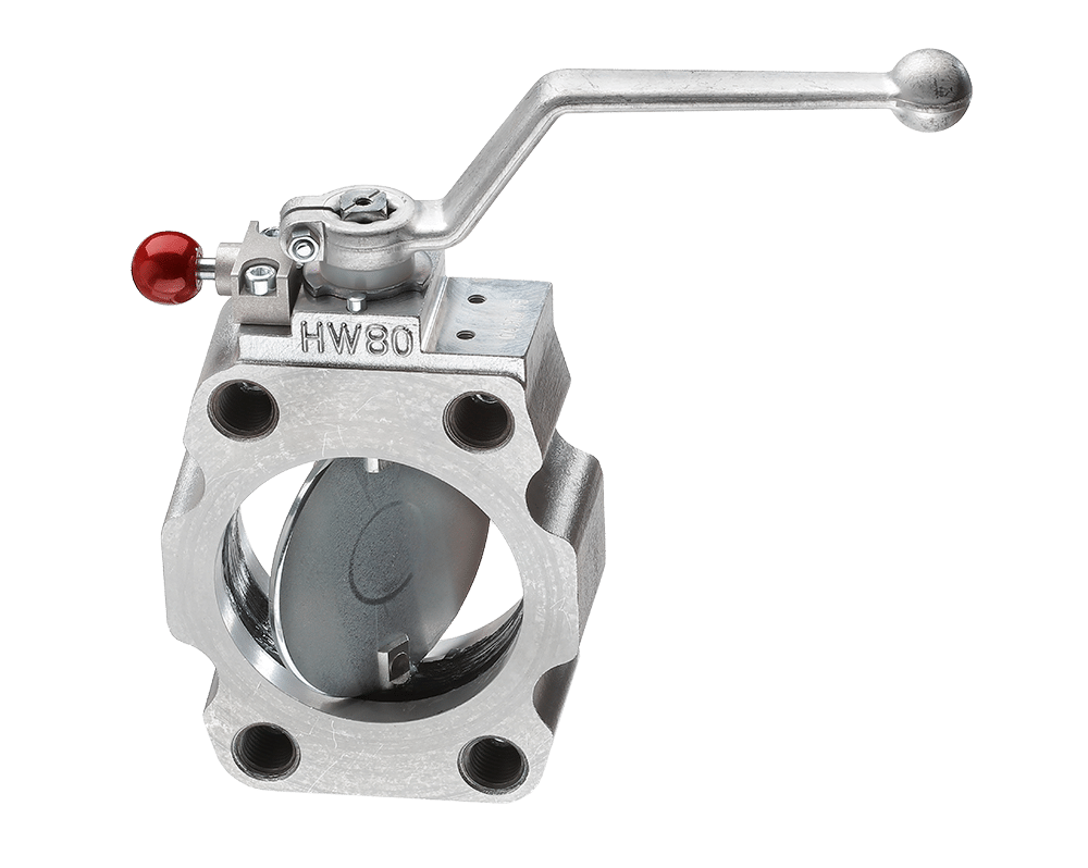
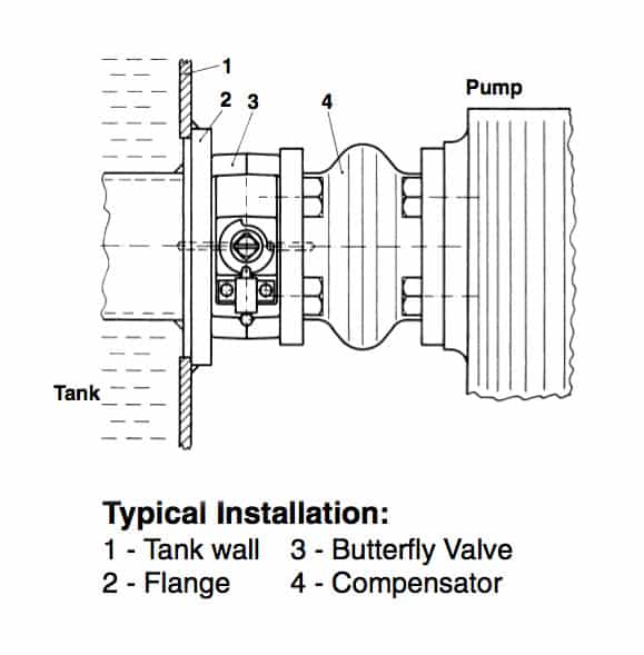
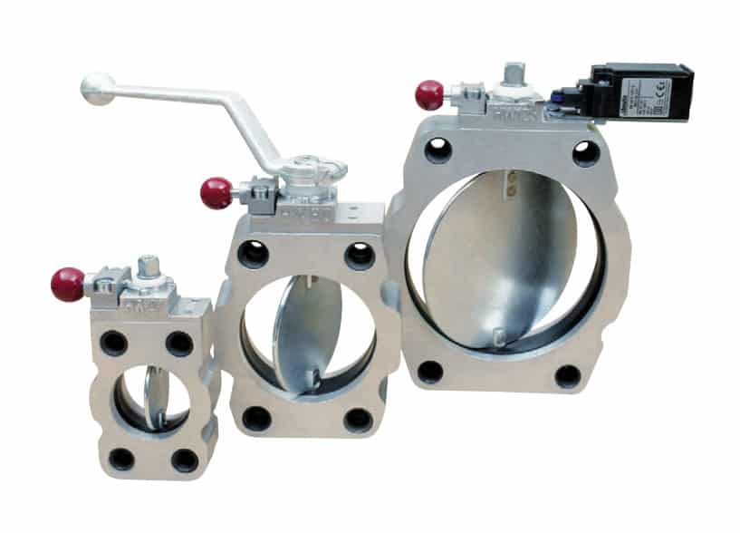
The Hytorc butterfly valve is a component designed to save time for the technician working on the hydraulic system by not having to drain the reservoir. The valve is designed for low pressure hydraulic lines up to 230 psi and can be installed into the pump suction line or mounted directly on to the hydraulic reservoir for example. The maximum pressure differential on either side of the valve should not exceed 58 psi when the valve is closed.
Hydraulic Butterfly Valves Features:
Thin profile and SAE flange for easy design into hydraulic circuits
Ideal for space limited mobile applications
28% more oil volume than ball valves
Simple maintenance; no reservoir draining
Equipped with a shifter for manual actuation
Easy installation for improved efficiency
Designed for low-pressure suction lines only
Automatic locking mechanism
Optional limit switch
Aluminum body for reduced weight
Low cost for large pipes
NBR seals ensure optimal sealing performance
Options: reservoir flange, limit switch, and threaded adapter brushing inserts
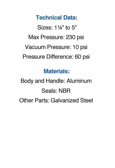
Technical Data and Specifications
Over pressure
232 psi (16.0 bar)
Under pressure
10 psi (0.7 bar)
Diff pressure when shut valve is closed
58 psi (4.0 bar)
Temperature range
-4ºF to 176ºF (-20ºC to 80ºC)
Material (Cage and Shifter)
Aluminum
Material (Sealings)
Nitrile Rubber (NBR) (Perbunan)
Material (Other Parts)
Galvanized Steel
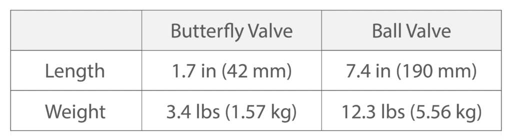
Comparing Size: Butterfly Valve versus Ball Valve on 4″ Pipe
For a 4″ pipe, butterfly valves are nearly 77% shorter and 71% lighter than a ball valve of the same diameter.
Ultra-compact profile to minimize space requirement:
In applications where fitting ball valves into the design poses a challenge, butterfly valves provide an effective solution. These valves are significantly shorter and lighter than their counterparts, facilitating easier handling and installation. The advantages of this design become increasingly evident as the nominal diameter rises. This is particularly beneficial in mobile hydraulics where space is a premium.
Convenient, simplified maintenance:
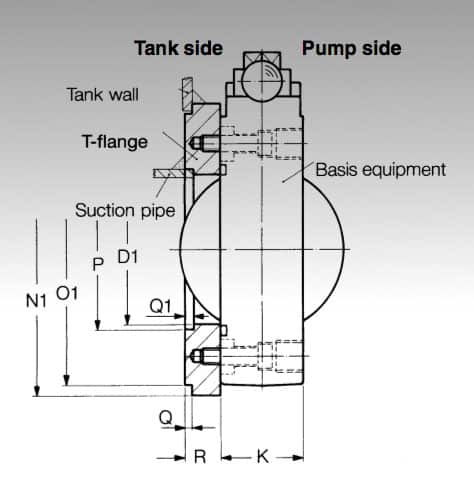
Thanks to internal clamping bolts, the valve is tightly secured to the reservoir even when even when disconnecting pipes or flexible connectors. This design enables maintenance without draining the reservoir.
Easy installation:
Shut off valves can be fitted between flanges due to the lateral recesses. Alternatively, heavy suction pipes can be held with additional screws.
No loss of oil volume:
The valve’s inner diameter is larger than the pipe, enabling full flow capacity without compromising on oil volume. This feature is crucial for maintaining efficient and precise control.
Automatic locking mechanism:
The self-engaging lock bar provides a secure and stable connection. The lock bar automatically engages in all switch positions; fully open, closed, or at an intermediate position, and ensures arresting of the valve’s position even without a shift lever.
Limit switch for preventative measures:
Prevent damage to your pump by making sure the valve is open prior to turning on the pump.
Ordering Code
AB 16 S [NG] – T H B E
The example for a shut off valve with a nominal width of 80mm, tank welded flange, shifter and limit switch is: AB 16 S 80 – THE
Hytorc is a supplier and power unit accessory and valve manufacturer for various applications including construction, mechanical, marine, and industrial.
Test Points and Test Hose Assemblies Pressure is one of the most important diagnostic parameters in the hydraulic circuit. Obtaining… Read More »Test Points & Test Hose Specs
Smart Logger Pressure Gauge Smart Logger Bluetooth digital pressure gauges incorporate a high precision pressure sensor with an accurate LCD… Read More »Smart Logger Pressure Gauge
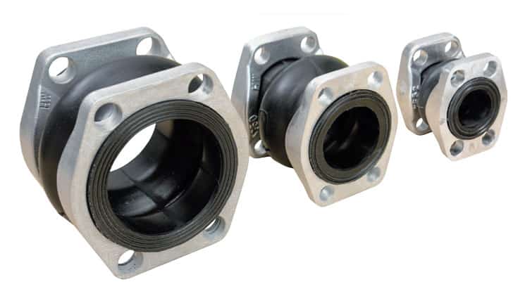
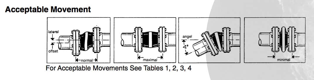
The HYTORC Rubber Compensator is a product that qualifies as one of the best kept secrets of power unit accessories. The compensators are flexible connectors with SAE or DIN flanges that correct pipe alignment problems. They also provide a benefit with damping of vibrations, noises and movements in axial and transverse direction.
The HYTORC Compensator is constructed of an inner liner of a reinforced high strength nitrile rubber (Perbunan). The outer and inside layers are smooth and have an aerodynamic design that eliminates cavitation. Both ends have a vulcanized sealing surface, eliminating the need of additional seals. The maximum operating pressure is 116 psi (6 bar) from -4 °F to +176 °F (-20ºC to 80ºC).
All types of mineral oil products, crude oil, lubricants, coolants, grease, cold water, warm water up to 140ºF (60ºC), water-oil-emulsion, fuels with up to 30% aromatics content
Ordering Code
K 16 S D – 80
The above example shows a compensator of a nominal width of 80mm with 1 SAE flange and 1 DIN flange.
HYTORC product designation
Form of execution, flange 1
S
Aluminum Alloy
ST
Galvanized Steel (SAE Flange)
D
Galvanized Steel (DIN Flange)
R
Malleable Cast Iron, Galvanized
Form of execution, flange 2
S
Aluminum Alloy
ST
Galvanized Steel (SAE Flange)
D
Galvanized Steel (DIN Flange)
R
Malleable Cast Iron, Galvanized
Nominal size
Hytorc is a supplier and power unit accessory and valve manufacturer for various applications including construction, mechanical, marine, and industrial.
Test Points and Test Hose Assemblies Pressure is one of the most important diagnostic parameters in the hydraulic circuit. Obtaining… Read More »Test Points & Test Hose Specs
Smart Logger Pressure Gauge Smart Logger Bluetooth digital pressure gauges incorporate a high precision pressure sensor with an accurate LCD… Read More »Smart Logger Pressure Gauge