Gear Flow Dividers
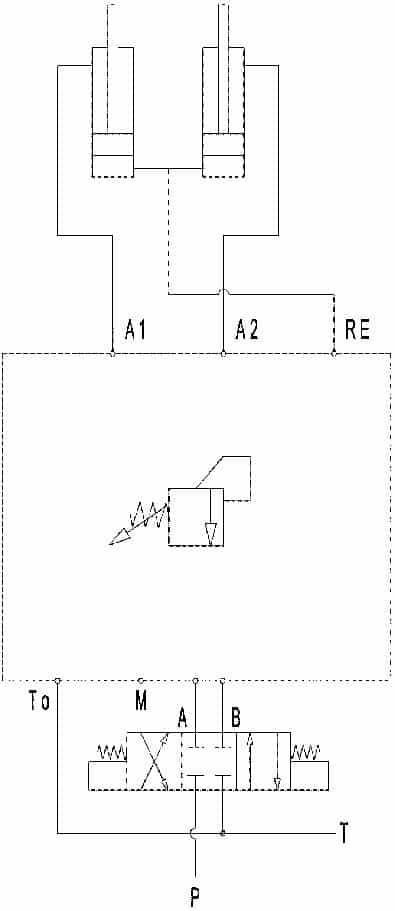
A flow divider is used to divide flow from a hydraulic pump into two or more output sections. Depending on the application, flow dividers can distribute flow into unequal or equal parts, but are normally used to provide the same output flow to multiple hydraulic components such as cylinders to ensure that they move the same amount.
Flow dividers synchronize movement of downstream hydraulic components.
How Do Gear Flow Dividers Work?
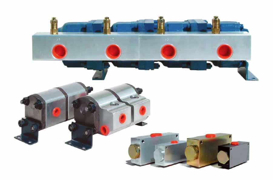
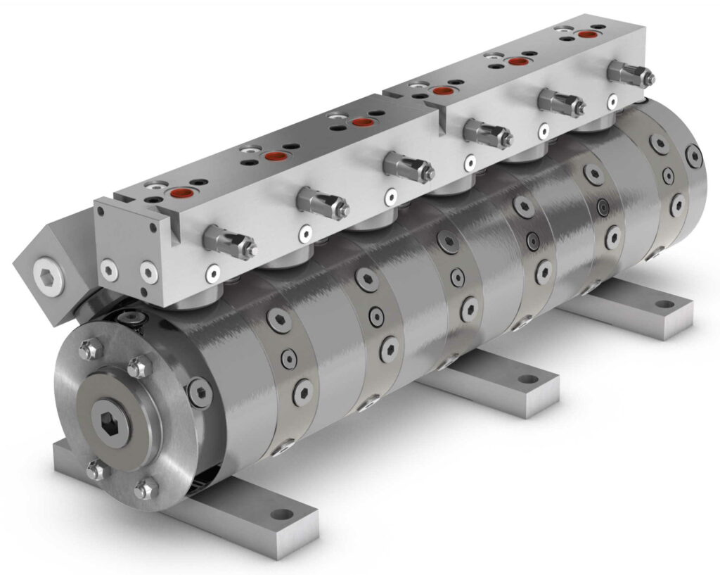
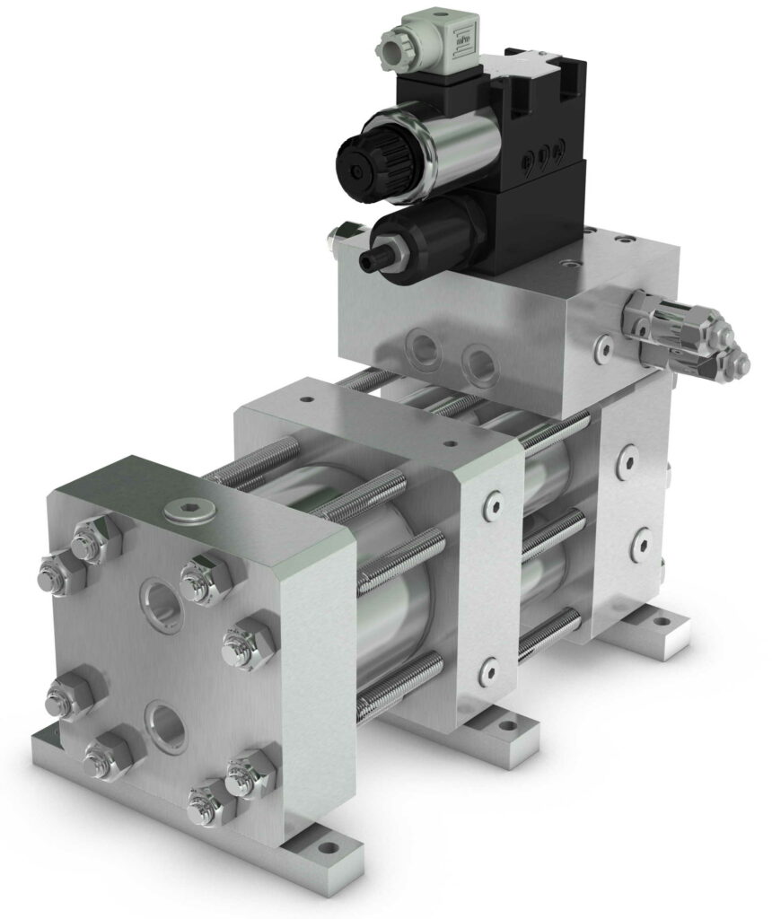
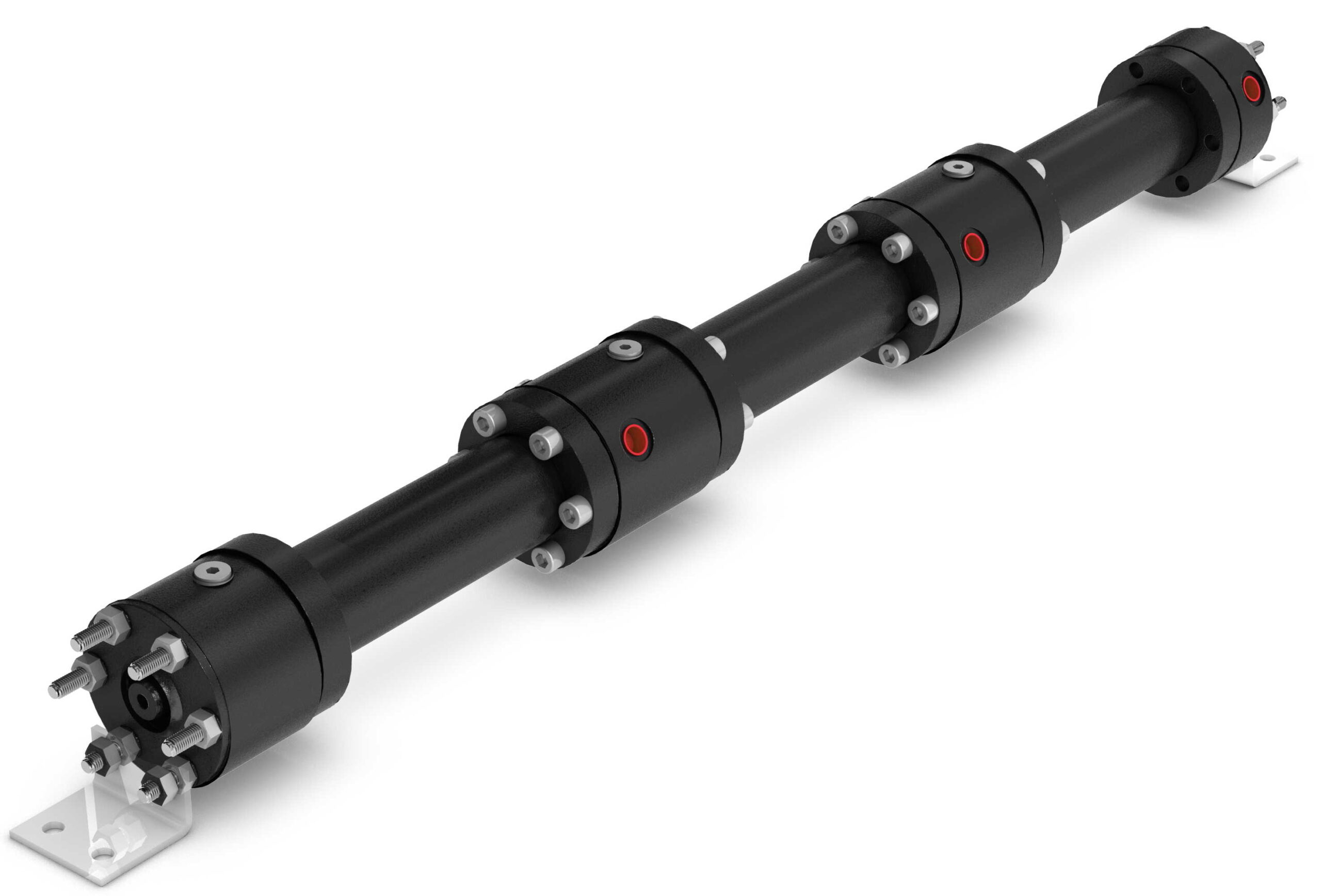
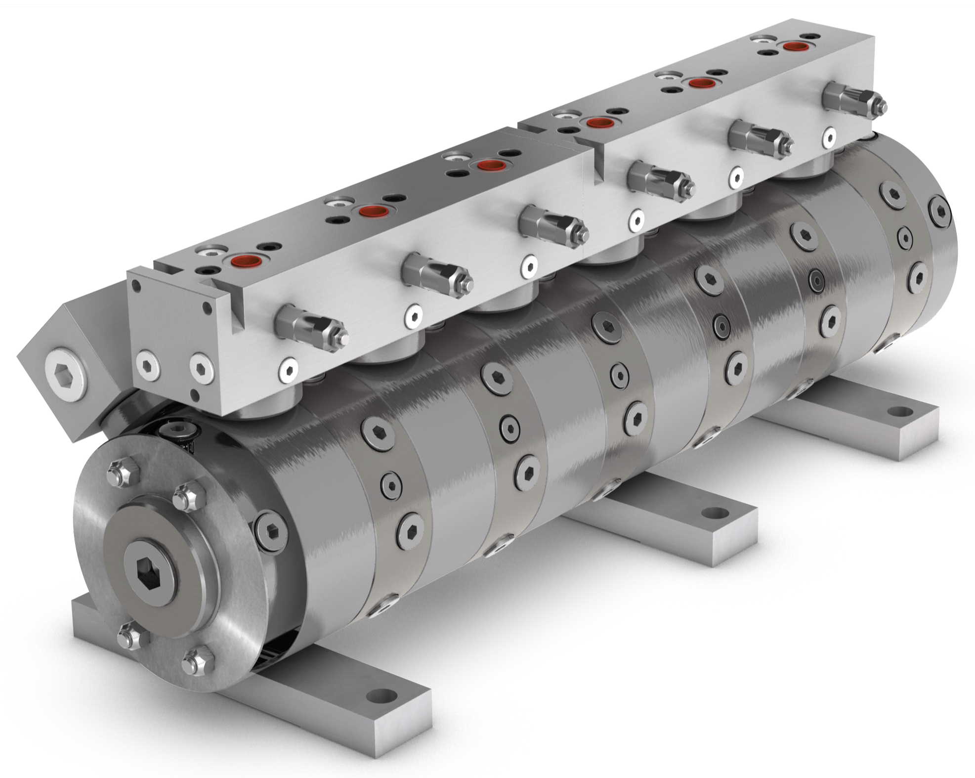
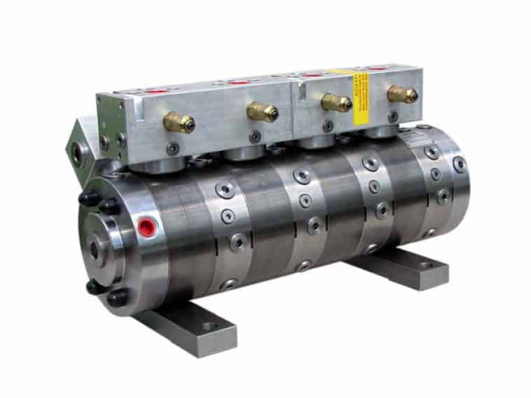
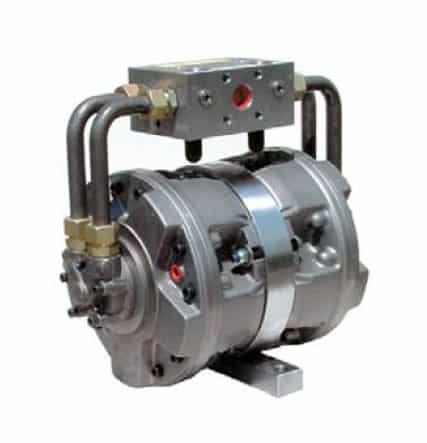
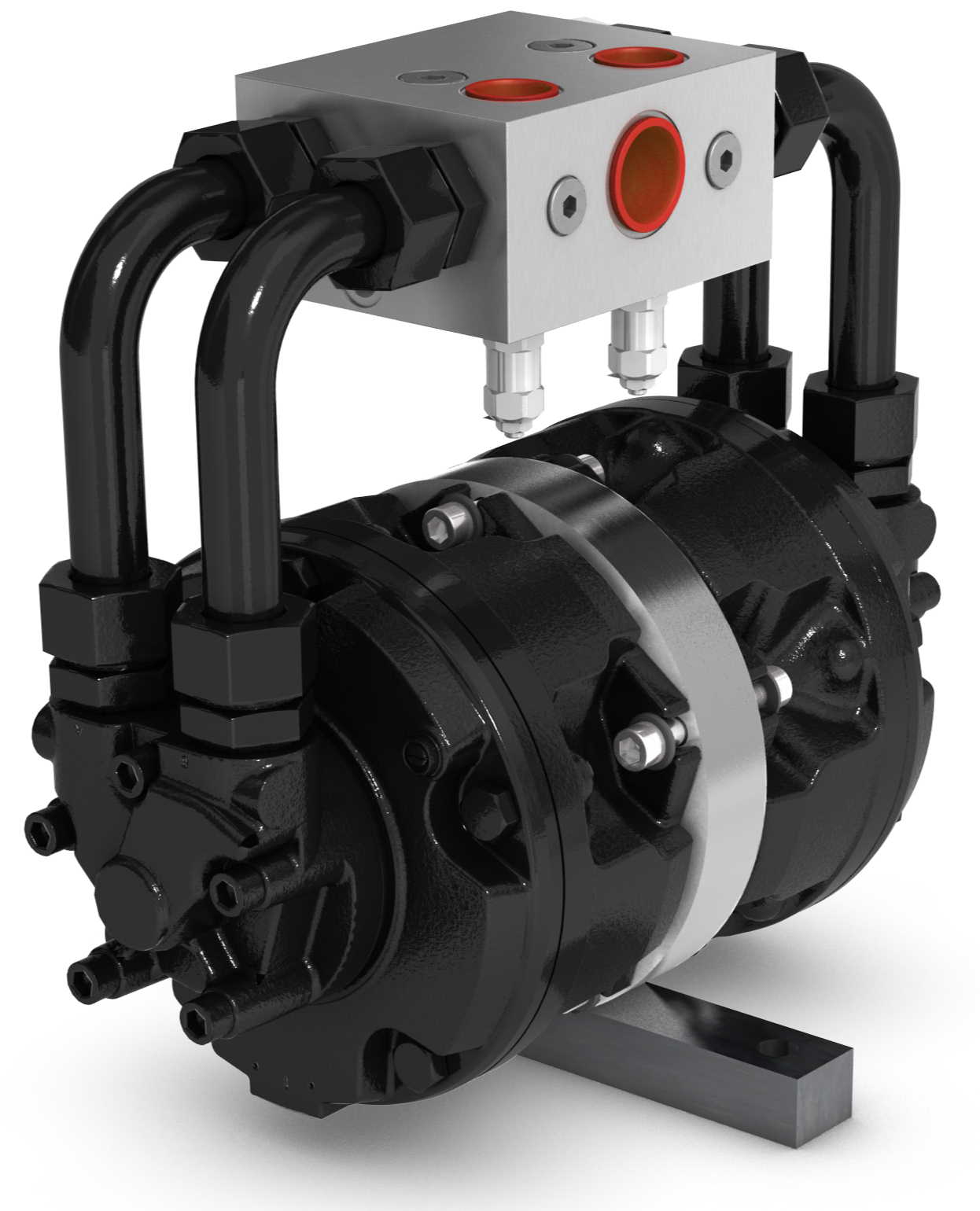
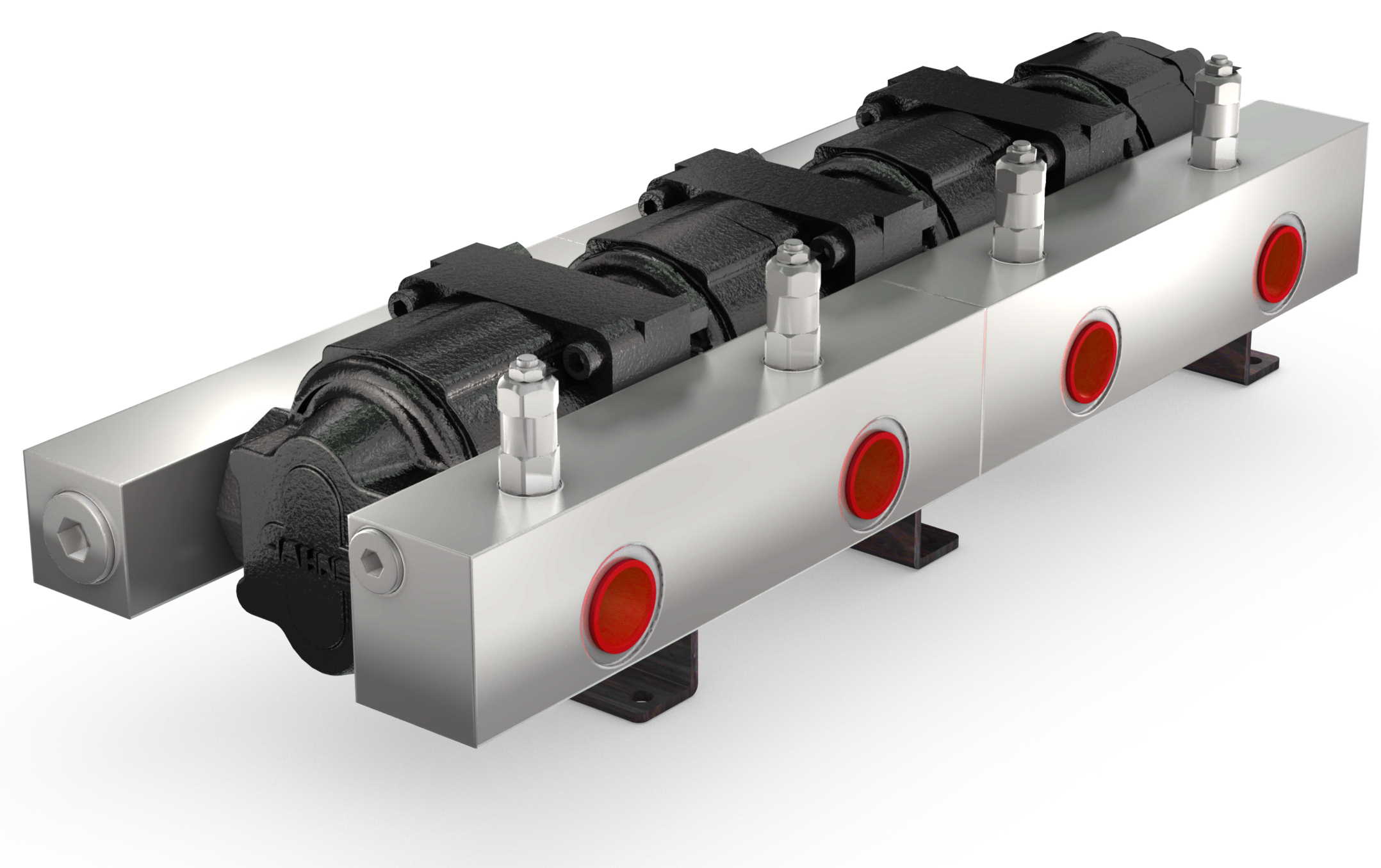
Gear flow dividers are made up of two or more hydraulic motors that are connected by a shaft. The shaft maintains the speed of the motors and ensures that it is equal so that the flow is distributed the same.
Benefits of using Gear Flow Dividers
Gear flow dividers are a cost-effective way to divide flow without losing a large amount of energy or heat. Furthermore, gear flow dividers are tolerant of contamination over other dividers, like spool flow dividers. They are the easiest and most cost-effective way to divide and provide flow to multiple hydraulic components at the same time.
Common Application of Gear Flow Dividers
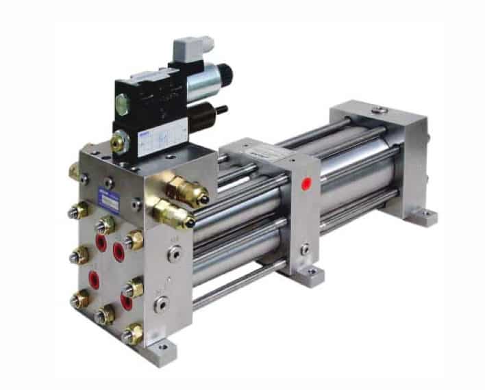
Two common functions of gear flow dividers include synchronizing fluid motors and hydraulic cylinders, and intensifying pressure in hydraulic pumps.
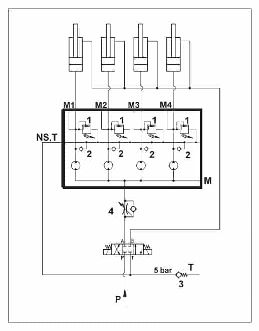
In the case where multiple cylinders need to move something in sync, gear flow dividers are often a great solution. This is useful, for example, in lifting platforms, where the platform must be lifted evenly and precisely by multiple cylinders. The platform must remain level to prevent binding in the guiding mechanism as well as for the objects on the top of the platform.
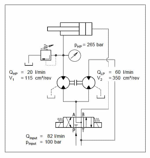
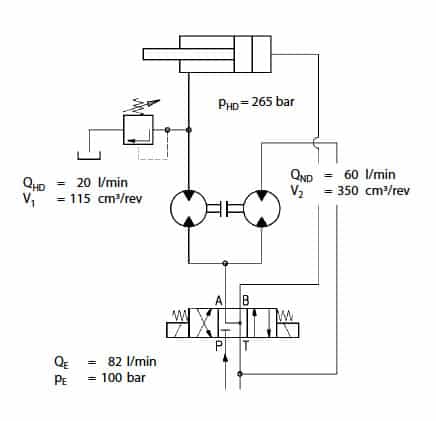
Flow dividers can be utilized as a pressure multiplier or intensifier. This type of hydraulic circuit can be used where a low-pressure circuit is already in use and where there is only need of small high-pressure flow. Since gear motor flow dividers offer a minimal loss of internal pressure at a low cost, this is an optimal solution.
Gear flow dividers can also be used as a hydraulic pressure intensifier for press and clamping circuits. In this application, the gear flow divider intensifies pressure by combining high flow fluid from the sections of the divider. From there, the outputs are discarded to the tank, which increases the pressure in the circuit.
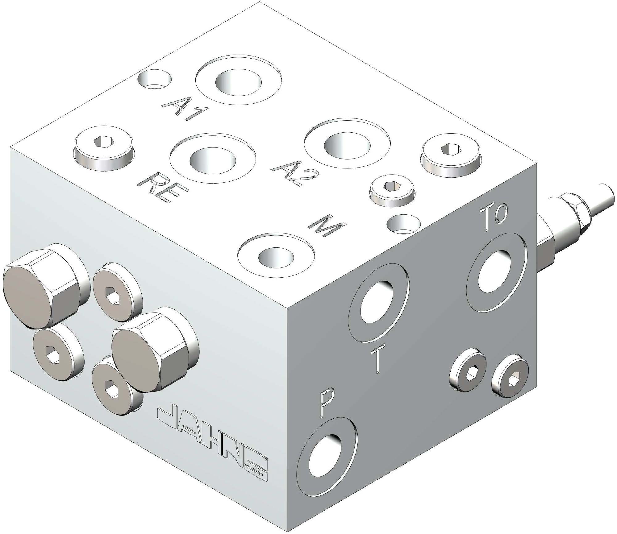
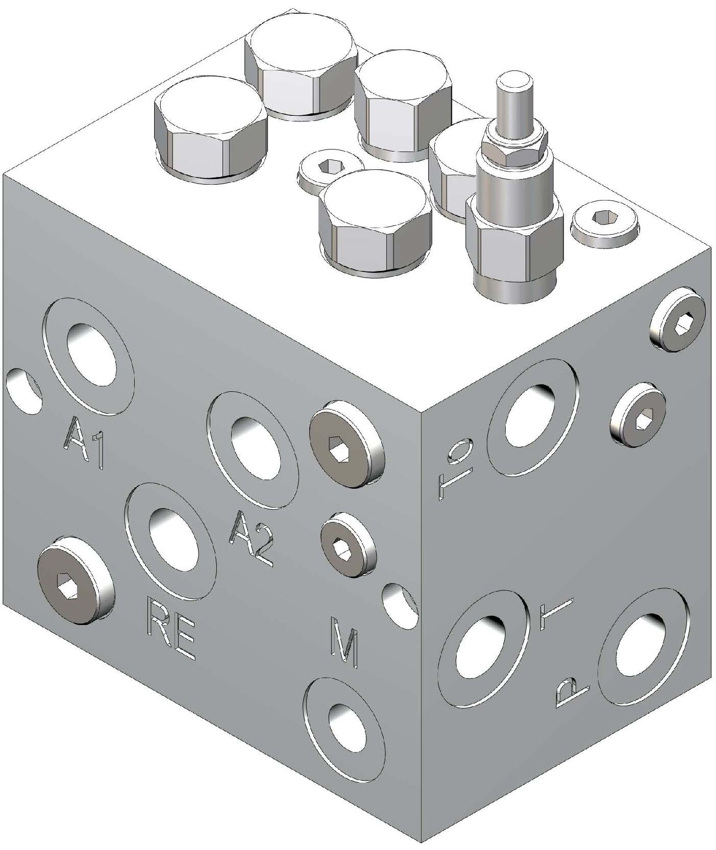
Our flow dividers are available with or without pressure relief valves to protect hydraulic systems from excessively high pressures.
How to Choose the Type of Gear Flow Divider
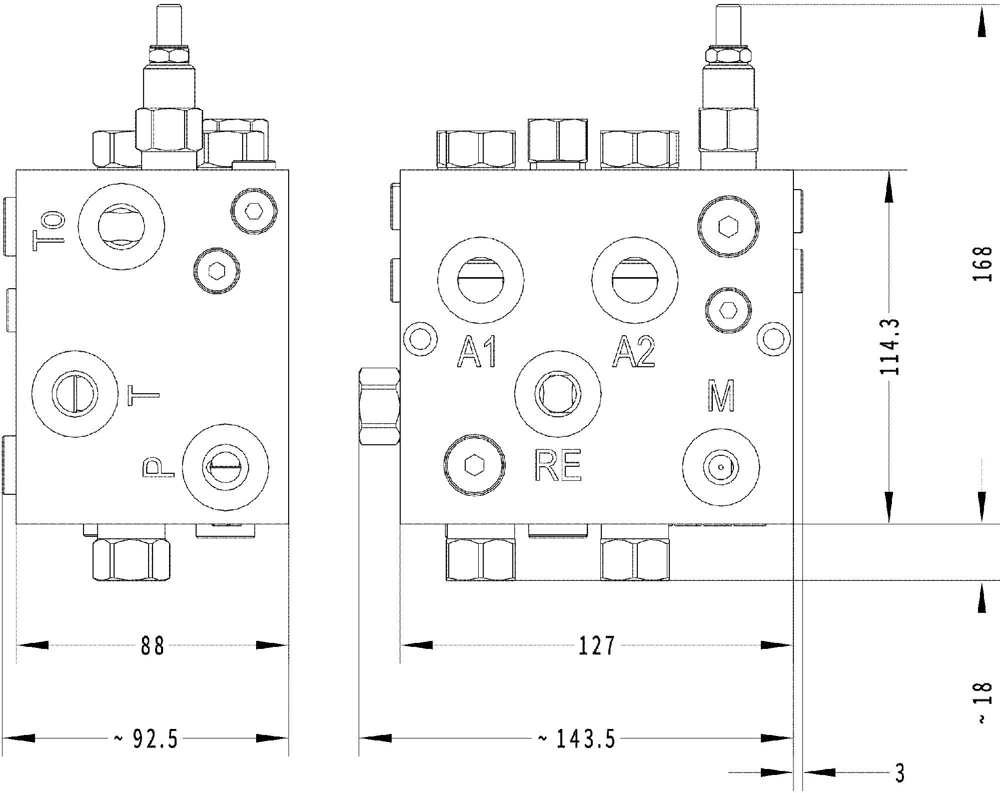
The flow rate, pressure, and required accuracy are all parameters to consider when choosing a model.
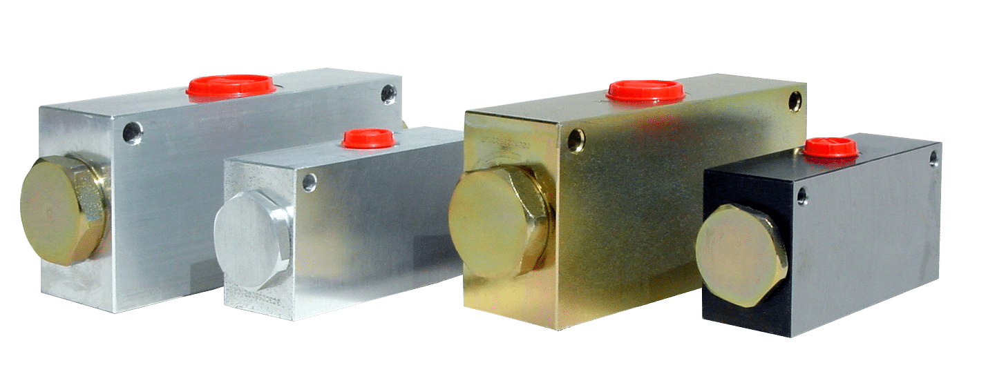
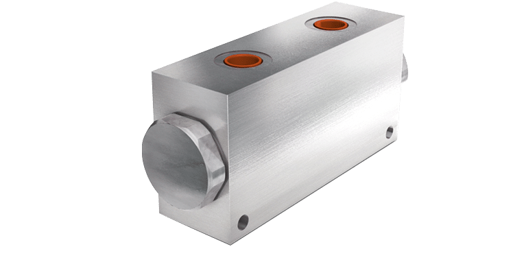
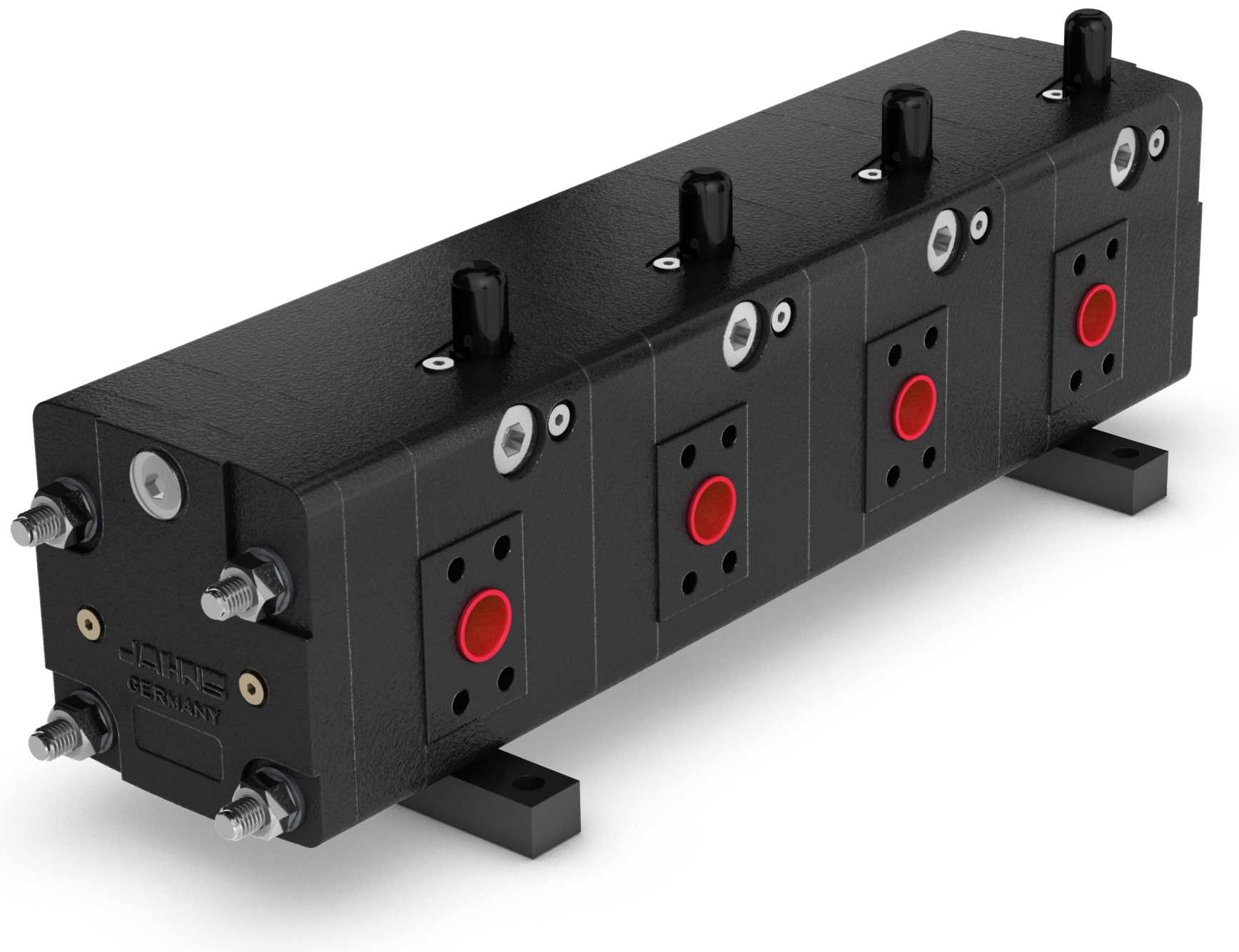
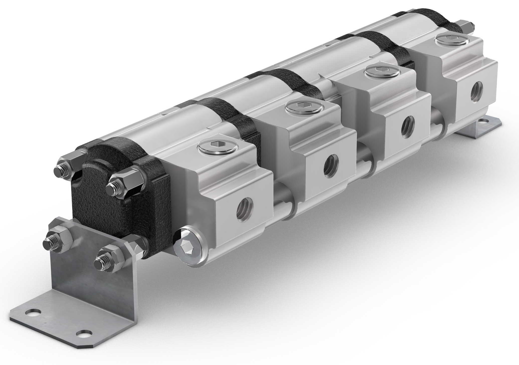
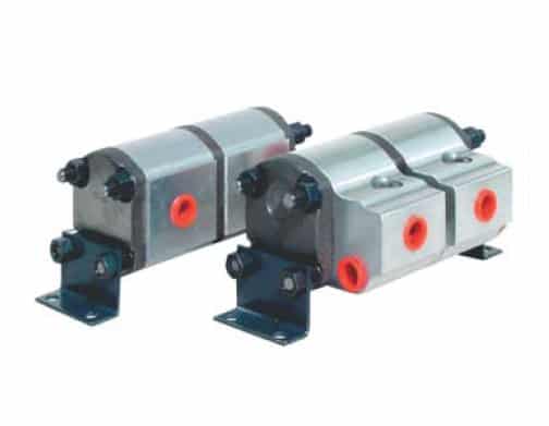
Our Hydraulic Gear Flow Divider MTO with aluminum housing has a flow rate of 0.4 gpm/1.5 lpm to 16 gpm/61 lpm with a working pressure up to 3625 psi/250 bar. This model also comes in cast iron housing, which can achieve a flow rate of 3 gpm/11.3 lpm to 58 gpm/220 lpm per section with a working pressure of 3900 psi/269 bar.
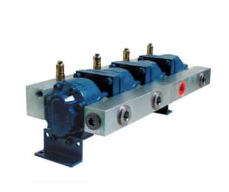
Our third option, the Hydraulic Gear Flow Divider HTO has a flow rate of 3 gpm/11.4 lpm to 37 gpm/140 lpm per section and a working pressure up to 4600 psi/317 bar.In addition to gear flow dividers, there are also radial piston and valve-type flow dividers as well as volumetric flow dividers. These are selected based on the same parameters of flow rate, pressure, and accuracy.
In terms of accuracy, our flow dividers have a high degree of synchronization even with the simpler gear-motor flow dividers. This high degree of synchronization is also maintained over a wide range of flows and is maintained with differing load conditions due to low leakage rates in the individual section.
The MTO model with aluminum housing runs more than 1200 rpm and has synchronization tolerances at ± 1.5 up to ± 2.0 %. The MTO model with cast iron housing and HTO model have synchronization tolerances at ± 3 up to ± 4%.
With reference to the gear-motor flow dividers MTO, synchronization differences depend on a range of parameters. For example, the oil viscosity and temperature; pressure load variability; system pressure levels; and the total flow rate to be divided, affect synchronization levels. Precise indications of synchronization levels are only possible if the details of all the parameters mentioned are known.
In addition to gear flow dividers, there are also radial piston and valve-type flow dividers as well as volumetric flow dividers. These are selected based on the same parameters of flow rate, pressure, and accuracy.