Skip to content

P12 Pro Servo Proportional Valve FAQs

The P12 Pro has a flow rate of 42 to 153 gpm (160 to 580 lpm) and response rate of <12 ms, the same flow capabilities of its S Series counterpart: the S12. The P12, however, features a lower response rate (S12: <6.5 ms) for applications where response time is not critical, but high flow is still necessary.

Flow Rate

Response Rate

P6 Pro

2.6 to 10.6 gpm (5 to 40 lpm)

<10 ms

P10 Pro

10.6 to 42 gpm (40 to 160 lpm)

<20 ms

P12 Pro

42 to 153 gpm (160 to 580 lpm)

<12 ms

Compare Domin P Servo Proportional Valves

Presses systems, power generation, industrial automation, wood & timber, metal processing, and marine.
 
The P12 Pro is designed for heavy duty applications with high flow rates (up to 153 gpm). It is specifically effective for applications with high loads and large-scale industrial environments including press systems, metalworking equipment, wood-processing machinery, and more.

Yes. The P12 Pro features a standard NG16 port pattern.

The P12 Pro is compatible with the NG16 mounting pattern/interface, also known as NG16 (CETOP 7), and ISO 4401-07-07.

Hydraulic Servo Proportional Valves – P12 Pro

Compact Power. Proven Reliability.

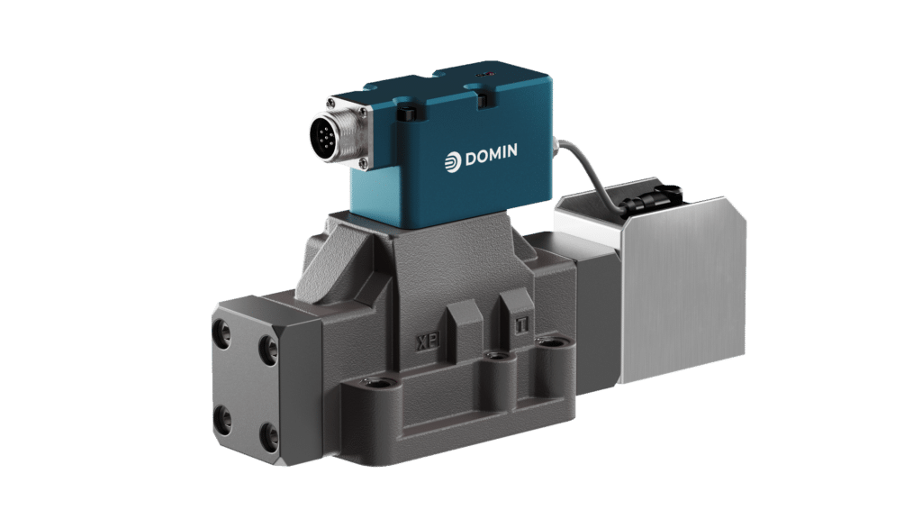
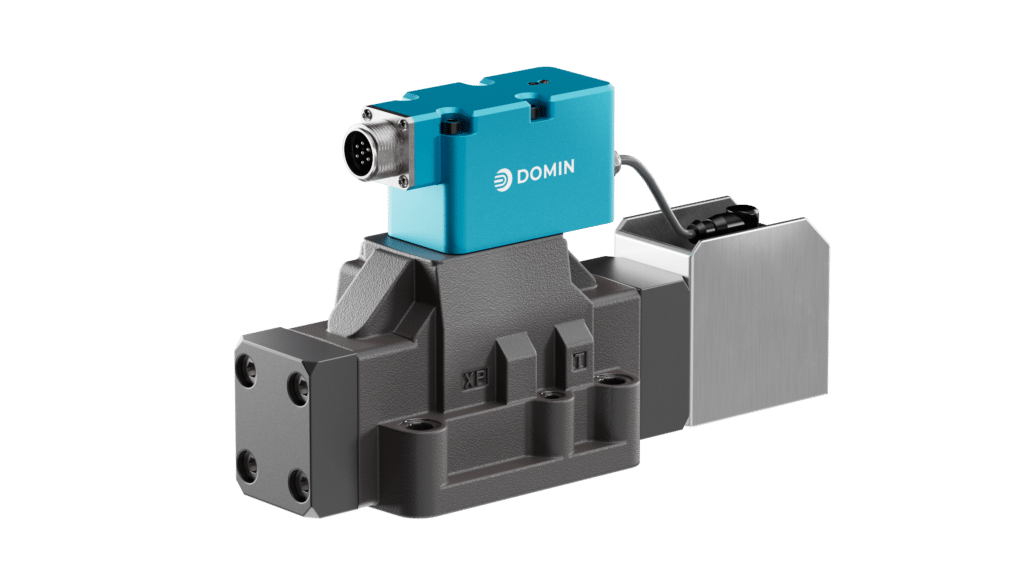
The P12 Pro is a two-stage hydraulic servo proportional valve designed for NG16 ports (CETOP 7). Its performance includes a flow range of 42-153 gpm (160-580 lpm), frequency over 60 Hz, and a response time of <12 ms. It is used for pressing applications and processing lines for ceramics and metal manufacturing. 

It delivers the required performance without the complexity of traditional servo valves, prioritising compact size, low mass, and robustness for continuous operation. Compatibility with standard NG16 interfaces enables easier commissioning, stable long-term behavior, and reduced maintenance in production systems.

For better performance (<6.5 ms response rate and >100 Hz frequency response) with the same maximum flow rate, view the S12 Pro. If you don’t need performance that is quite as dynamic (<20 ms response rate) with lower flow capabilities (42 gpm max), view the P10 Pro.

Popular Upgrade Models:

  • Bosch Rexroth 4WRLE 16
  • Moog D662
  • Parker D41FP
  • Atos DPZO-2

Key Stats:

  • Frequency Response: > 60 Hz
  • Rated Flow: 160 to 580 lpm (42 to 153 gpm)
  • Response Time: < 12 ms

Key Features:

  • Onboard electronics with spool position feedback
  • Rated flow of up to 580 lpm at 35 bar P per edge (153 gpm)
  • Based on the NG16 port pattern
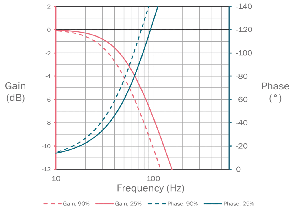
  • Bandwidth > 60 Hz (-3 dB, up to ± 25% of full stroke)
  • Low power consumption of less than 5 W

Standard Modification Options:

The P12 Pro is designed to be customized. Standard modifications include:

  • Choice of rated flows 160 to 580 lpm (42 to 153 gpm)
  • Multiple voltage or current control options
  • Various seal materials available
  • Non-standard configurations available

Technical Data:

Design

Two-Staged Servo Valve

Actuation

Direct Drive Pilot

Size

NG16

Mounting Interface

ISO 4401-07-07

Ambient Temperature

ºC (ºF)

-20 to +60
(-4 to +140)

Mass

kg (lb)

< 7 (15.4)

Vibration Resistance

g

10

Shock Resistance

g

15

IP

IP65

Max. Operating Pressure (P, A, B, X)Bar (psi)350 (5,000)
Max. Operating Pressure (Y, T)Bar (psi)250 (3,600)
FluidHydraulic Oil DIN 51524-535
Fluid TemperatureºC (ºF)-20 to +60
(-4 to +140)
ViscositycSt10 to 400
Rated Flow (35 Bar P per edge)l/min (US gal / min)580 (153)
Flow Maximuml/min (US gal / min)1000 (264)
Pilot Leakagel/min (US gal / min)1.3 (0.34)
Main Stage Leakagel/min (US gal / min)1.2 (0.32)
FiltrationISO 4406 (1999) 18/16/13
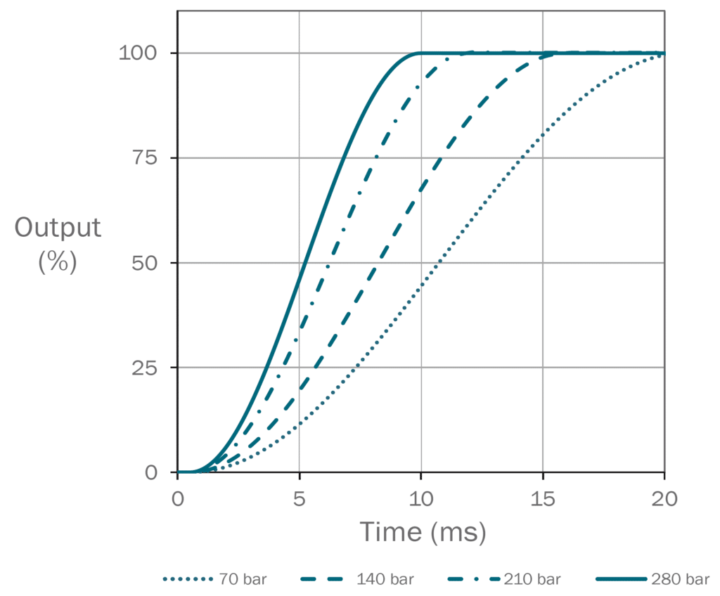
Response Time at 100% Step Inputms< 12
Frequency Response (-3dB gain, ±25% signal)Hz> 60
Frequency Response (-90deg phase, ±25% signal)Hz> 60
Hysteresis%< 0.2
Threshold%< 0.1
Null Shift%< 1

View performance graphs for the P12 Pro Domin Servo Valve below including Step Response and Frequency Response:
Type: Case Mounted
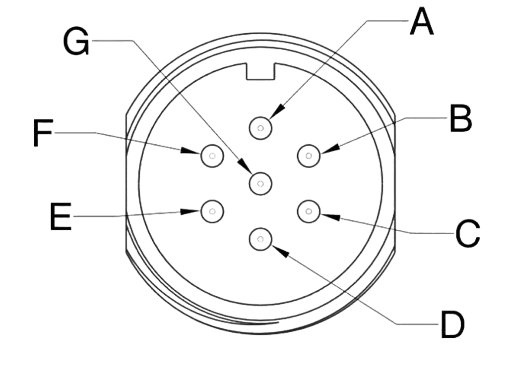
Termination: Connector according to EN 175201-804/MIL 5015 equivalent, shell size 14
Number of Contacts: 7

Pin

Function

Desc.

A

Supply +

+24 V

B

Supply 0 V

0 V

C

Output –
Enable Input

Output 0 V Reference
Drive Enable Input*

D

Input +

Differential Input, +

E

Input –

Differential Input, –

F

Output +

Output Signal

G

Earth

* When the enable function is selected, the function of pin C is the enable input. This replaces the standard pin function.

Type: Case Mounted
Termination: Connector according to EN 175201-804/MIL 5015 equivalent, shell size 14
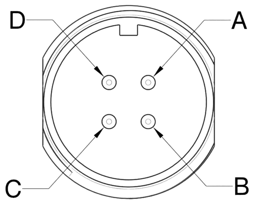
Number of Contacts: 4

Pin

Function

Desc.

A

Supply +

+24 V

B

Input +

Differential input signal, +

C

Input –

Differential input signal, –

D

Supply 0 V

0 V

* When the enable function is selected, the function of pin C is the enable input. This replaces the standard pin function.

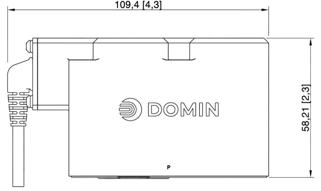
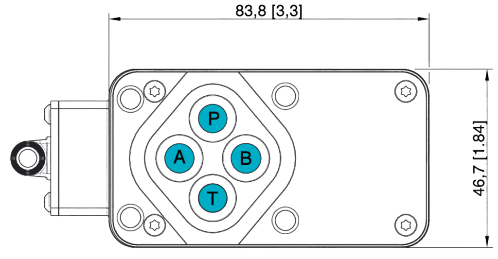
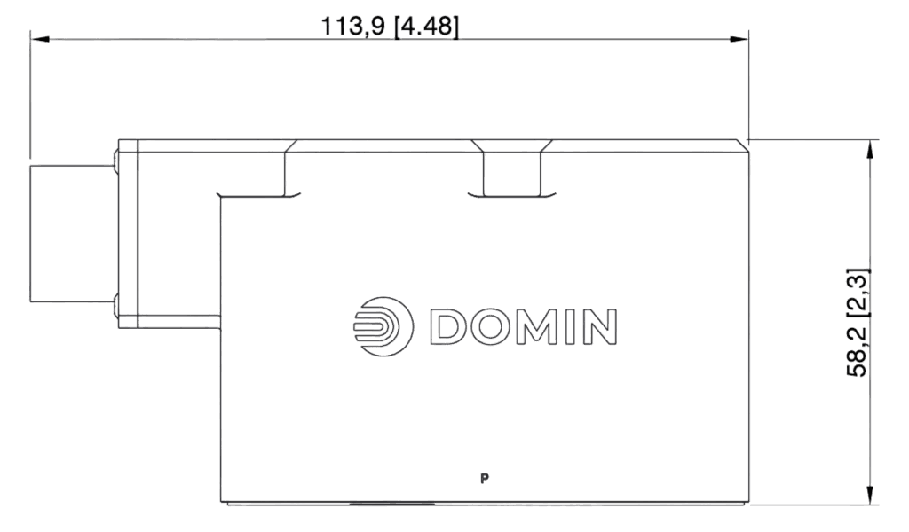
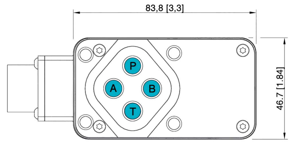
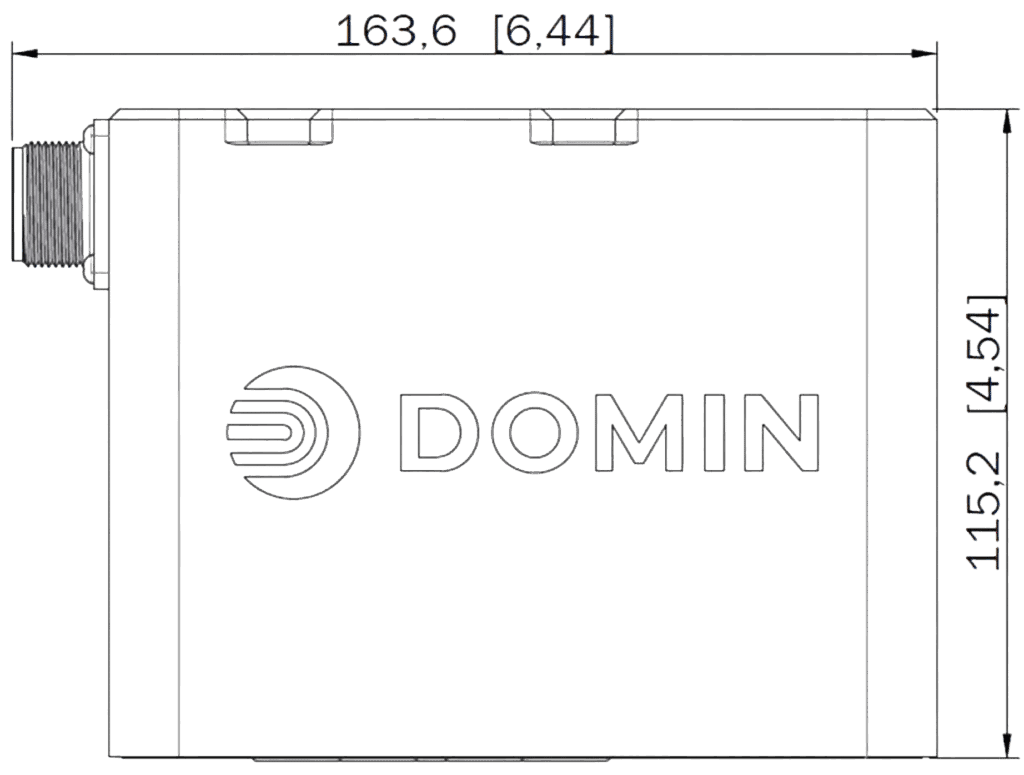
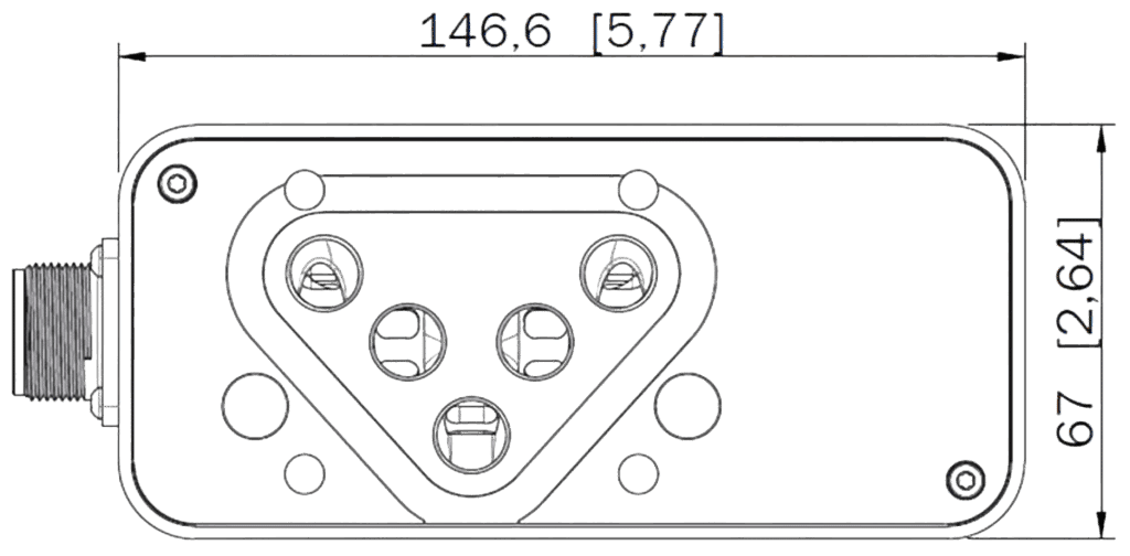
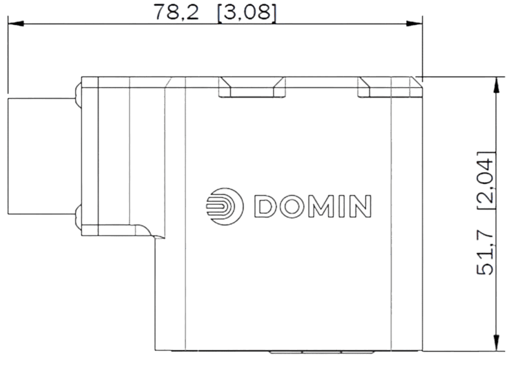
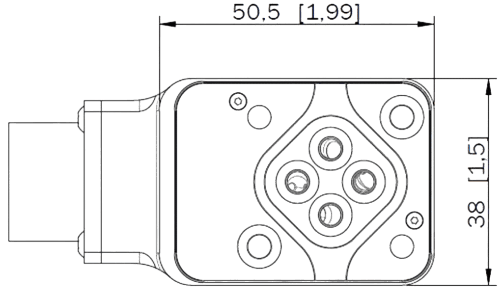
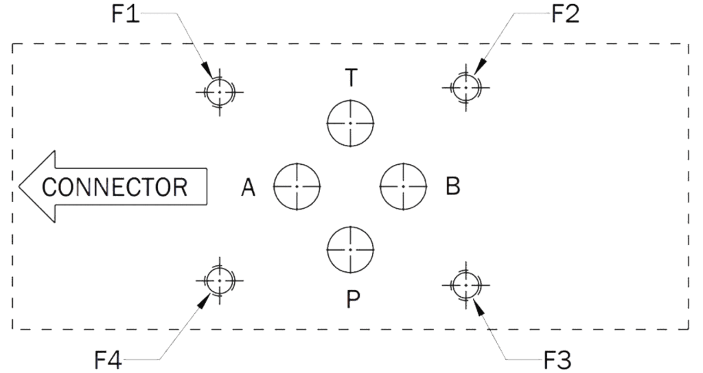
Unit Dimensions

Nominal dimensions are displayed in mm. Bracketed dimensions are in inches. Not to scale.

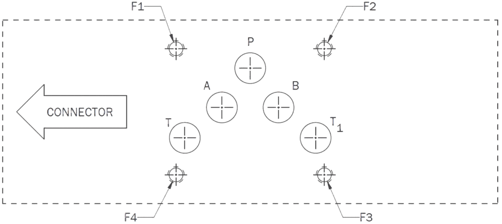
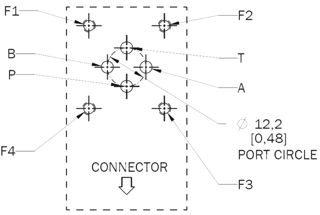
Mounting Surface Pattern

Dia Ø
mm

X Position
mm

Y Position
mm

P

20

50

14.3

A

20

34.1

55.6

B

20

65.9

55.6

T

20

18.3

14.3

L

6.3

0

34.9

X

6.3

76.6

15.9

Y

6.3

88.1

57.2

F1

M10

0

0

F2

M10

101.6

0

F3

M10

101.6

69.9

F4

M10

0

69.9

F5

M6

34.1

-1.6

F6

M6

50

71.5

* Valves includes seal grooves for X and Y ports for installation in existing systems X and Y connections are NOT required for valve operation.

Bolts (F1, F2, F3, F4)

Type: M10 x 50 mm DIN EN ISO 4762-8.8
Req.Torque: 40 Nm (29.5 ft-lbf)

Bolts (F5, F6)

Type: M6 x 50 mm DIN EN ISO 4762-8.8
Req.Torque: 8 Nm (5.9 ft-lbf)

O-Rings (P, A, B, T)

Type: 22.22 x Ø 2.62
Material: NBR or Viton, 90 Shore A

O-Rings (L, X, Y)

Type: 10.82 x Ø 1.78
Material: NBR or Viton, 90 Shore A

Standards Reference

EMC Regulations: Immunity: EN 61000-6-2, Emission: EN61000-6-3
Performance Tests: ISO 10770-1
Pressure Rating: ISO 10771
Hydraulics Interface: ISO 4401-07-07*

* Ports over-sized to Ø 20 mm.

Ordering Code

P12 Pro 1 2 3 4 5 6 7 8 9

Any value in range 250 to 580 l/min

R – Suffix for reversal of A and B port e.g. 200R

A

Axis cut (1% overlap linearized)

B

Float

D

Blocked

X

For other options please enquire

A

± 10 V

B

± 20 mA

C

4 to 20 mA

F

± 10 mA

G

± 50 mA

X

For other options please enquire

For differing input and output signals, use two letters,
e.g. AC denotes ± 10V input and 4 to 20 mA output

A

Axis

B

Float

C

Passive

D

Blocked

PA

A Bias

PB

B Bias

X

For other options please enquire

E

6 pin + PE circular connector

E4

4 pin

X

For other options please enquire

Y

Enable mode on

N

No enable functionality

X

For other options please enquire

R

Recommended – any hydraulic oil in accordance with DIN 51524.

X

For other options please enquire

N

Nitrile

V

Viton

X

For other options please enquire

Assigned individually to any with customized options upon enquiry

Variants on Request

Domin is proud of their ability to offer tailored solutions that meet customers’ specific needs. If you require a non-standard configuration, or a bespoke modification, we are confident we can provide you with the best solution. Talk to us here and one of our team will respond as soon as possible.

Domin is a supplier and servo valve manufacturer for various applications including high duty industrial machines, production & processing equipment, energy & process systems, and large-scale industrial automation.


P10 Pro Servo Proportional Valve FAQs

The P10 Pro has a flow rate of 10.6 to 42 gpm (40 to 160 lpm) and response rate of <20 ms. This valve is ideal for applications where the control tolerances are not as tight, as the response rate is the slowest of Domin’s valves. Applications that do not require extremely fast response rates with flow rates under 42 gpm (160 lpm) can use Domin’s P10 as a cost-effective option.

Flow Rate

Response Rate

P6 Pro

2.6 to 10.6 gpm (5 to 40 lpm)

<10 ms

P10 Pro

10.6 to 42 gpm (40 to 160 lpm)

<20 ms

P12 Pro

42 to 153 gpm (160 to 580 lpm)

<12 ms

Compare Domin P Servo Proportional Valves

Presses systems, power generation, industrial automation, wood & timber, metal processing, and marine.
 
The P10 Pro is designed for heavy duty applications with high flow rates (up to 42 gpm). It is specifically effective for applications with high loads and large-scale industrial environments including press systems, metalworking equipment, wood-processing machinery, and more.

Yes. The P10 Pro features a standard NG10 port pattern.

The P10 Pro is compatible with the NG10 mounting pattern/interface, also known as CETOP 5, S77, and ISO 4401-05-04.

Hydraulic Servo Proportional Valve – P10 Pro

The P10 Pro is a high flow hydraulic servo proportional valve designed for NG10 ports (CETOP 5). Its performance includes a flow range of 10.6-42 gpm (40-160 lpm), frequency over 65 Hz, and a response time of <20 ms. It is designed for pressing, power and energy, and large-scale industrial automation. It is designed for environments where consistent control under higher loads is essential.

For higher performance capabilities (<7 ms response rate and 66 gpm flow maximum compared to P10’s <20 ms response rate and 42 flow maximum), refer to the S Series counterpart, the S10 Pro. If you need less flow, but better response rates (<10 ms response rate and 10.6 gpm flow maximum), the P6 Pro offers a cost-effective solution.

Available on NG10 port pattern as standard. S77 adaptors available.

Popular Upgrade Models:

  • Bosch Rexroth 4WRPEH 10
  • Woodward 27G50F
  • Atos DLHZ0
  • Moog D634

Key Stats:

  • Hysteresis: <0.2%
  • Leakage: <0.4 gpm (<1 lpm)
  • Shock Resistance: 50 g
  • Frequency Response: >65 Hz
  • Rated Flow: 10.6 to 42 gpm (40 to 160 lpm)
  • Flow Maximum: 66 gpm (250 lpm)
  • Response Time: <20 ms
  • Mounting Interface: ISO 4401-05-04

Key Features:

  • Onboard electronics with spool position feedback
  • Rated flow of up to 160 lpm at [1,015 psi (70 bar)]
  • Based on the NG10 port pattern
  • Bandwidth > 65 Hz (-3 dB, up to ± 25% FS)
  • Chip shear capability of >157 lbf (>700 N)
  • Valve mass of 8.8 lb (4 kg)

Standard Modification Options:

  • Rated flow rates of up to 42 gpm (160 lpm)
  • Multiple voltage or current control options
  • Various seal materials available
  • Non-standard configurations available

Technical Data:

DesignDirect Drive Servo Proportional Valve
ActuationRotary-Linear
SizeNG10
Mounting InterfaceISO 4401-05-04
Ambient TemperatureºC (ºF)-20 to +60 (-4 to +140)
Masskg (lb)4 (8.8)
Vibration Resistanceg30
Shock Resistanceg50
Max. Operating Pressure (P, A, B)Bar (psi)350 (5,000)
Max. Operating Pressure (T)Bar (psi)250 (3,600)
FluidHydraulic Oil DIN 51524
Fluid TemperatureºC (ºF)-20 to +80 (-5 to +175)
ViscositycSt5 to 500
Rated Flowl/min (US gal / min)40 to 160
(10.6 to 42)
Flow Maximuml/min (US gal / min)250 (66)
Pressure Gain% / %>40
Leakage at 100 barl/min (US gal / min)<1 (0.4)
FiltrationISO 4406 (1999) 18/16/13
Response Time at 100% Step Inputms<20
Frequency Response (-3dB gain, ±25% signal)Hz>65
Frequency Response (-90deg phase, ±25% signal)Hz>65
Hysteresis%<0.2
Threshold%<0.1
Null Shift%<1

View performance graphs for the P10 Pro Domin Servo Proportional Valve below including Step Response and Frequency Response:

Ordering Code

P10 Pro 1 2 3 4 5 6 7 8 9

Any value in range 40 to 160

Rate flow in l/min for 35 bar ∆P per control edge

R – Suffix for reversal of A and B port e.g. 250R

A

Axis cut (1% overlap linearized)

D

Deadband

F

Float Center

O

Overlap

X

For other options please enquire

A

± 10 V

B

± 20 mA

C

4 to 20 mA

D

± 5 V

E

± 5 mA

F

± 10 mA

X

For other options please enquire

For differing input and output signals, use two letters,
e.g. AC denotes ± 10V input and 4 to 20 mA output

C

Center

X

For other options please enquire

E

6 pin + PE circular connector *

E4

4 pin circular connector *

X

For other options please enquire

* EN 175201-804/MIL 5015 equivalent connector, shell size 14

Y

Enable mode on

N

No enable functionality

R

Recommended – any hydraulic oil in accordance with DIN 51524, filtered in accordance with ISO4406 18/16/13. Compatibility with water-free synthetic fluids available on enquiry.

X

For other options please enquire

N

Nitrile (Shore 90)

V

Viton (Shore 85)

X

For other options please enquire

Assigned individually to any with customized options upon enquiry

Variants on Request

Domin is proud of their ability to offer tailored solutions that meet customers’ specific needs. If you require a non-standard configuration, or a bespoke modification, we are confident we can provide you with the best solution. Talk to us here and one of our team members will respond as soon as possible.

Domin is a supplier and servo valve manufacturer for various applications including blow/injection molding, wood/timber machines, metal processing, die casting, hydraulic presses, and vibration equipment.


P6 Pro Servo Proportional Valve FAQs

The P6 Pro has a flow rate of 2.6 to 10.6 gpm (5 to 40 lpm) and response rate of <10 ms. It is the fastest valve in the P Series, ideal for applications that do not need the speed of the S6 Pro (<3.5 ms), but have a similar flow rate.

Flow Rate

Response Rate

P6 Pro

2.6 to 10.6 gpm (5 to 40 lpm)

<10 ms

P10 Pro

10.6 to 42 gpm (40 to 160 lpm)

<20 ms

P12 Pro

42 to 153 gpm (160 to 580 lpm)

<12 ms

Compare Domin P Servo Proportional Valves

Injection molding, ceramics pressing, industrial automation, metal processing, wood & timber, and marine.
 
The P6 Pro is designed for precise motion control in small to mid-sized industrial systems, such as injection molding, ceramic forming presses, automated handling systems, and more.

Yes. The P6 Pro features a standard NG06 port pattern.

The P6 Pro is compatible with the NG06 mounting pattern/interface, also known as CETOP 3, and ISO 4401-03-02. Additionally, a S04 adapter is available.

For most injection molding presses, the Domin P Series is an optimal choice for industrial presses as it focuses on durable and stable day to day motion control.
 
The P6 Pro can be simply integrated into the system and is more cost-effective for applications that do not require highly dynamic performance. Learn how the P Series addresses control challenges in injection molding.

Hydraulic Servo Proportional Valve – P6 Pro

The P6 Pro is a robust hydraulic servo proportional valve designed for NG06 (CETOP 3) ports. Its performance includes a flow range of 1.3-10.6 gpm (5-40 lpm), frequency over 100 Hz, and a fast response time of <10 ms. This model offers a cost-effective alternative to the S6 Pro and is made for applications with more flexible response times. It offers affordable pricing for industrial quantities in metal processing, ceramics, injection molding, wood and timber, and more. 

It is designed for smaller and mid-sized industrial systems. Its fast response and fine resolution make it well suited to machinery that depends on accurate motion management in a smaller footprint. It installs easily into existing NG06 platforms and brings dependable day to day performance with minimal setup.

Servo Proportional Valves Designed for Industrial Applications

The P Series is designed for industrial and automation applications, such as injection molding equipment, ceramic presses, energy systems, and automated production lines. See how it compares to Domin’s original S Series in industrial applications:

P Series

S Series

  • Accessible pricing for high-volume industrial applications
  • Designed for robust industrial manufacturing, molding, and automation
  • Applications for low to medium response rates (<10 ms for NGO6)
  • Competitive pricing with better performance compared to big names in the servo valve market
  • Designed for testing and dynamic applications
  • Applications for fast response rates (<3.5 ms for NGO6)

If you need faster response rates (<3.5 ms compared to P6 Pro’s <10 ms), view the S Series counterpart, the S6 Pro, our most popular model. The S6 Pro also offers a slightly higher flow maximum (15.9 gpm / 60 lpm compared to P6 Pro’s 10.6 gpm / 40 lpm). If you are looking for even higher capabilities, the P10 Pro offers a maximum flow rate of 42 gpm (160 lpm).

Popular Upgrade Models:

  • Moog D633: 75% lighter
  • Bosch Rexroth 4WRPEH 6
  • Atos DLHZO
  • Woodward 27B50F

Key Stats:

  • Hysteresis: <0.2%
  • Leakage: <0.13 gpm (<0.5 lpm)
  • Mass: 1.39 lbs (0.63 kg)
  • Rated Flow: 1.3-10.6 gpm (5-40 lpm)
  • Response Time: <10 ms

Key Features:

  • Onboard electronics with spool position feedback
  • Rated flow of up to 10.6 gpm (40 lpm) (at 1,015 psi (70 bar))
  • Mounting interface of ISO 4401-03-02
  • Available on NG06/CETOP3 port pattern as standard
  • Bandwidth > 100 Hz (-3 dB, up to ± 25% FS)
  • Low power consumption of less than 5 W 
  • Chip shear capability of greater than 89 lbf (400 N)
  • Low weight of less than 1.5 lbs (630 g)

Standard Modification Options:

  • Choice of rated flow up to 10.6 gpm (40 lpm)
  • Multiple voltage or current control options
  • Various seal materials available
  • Non-standard configurations available

Technical Data:

DesignDirect Drive Servo Proportional Valve
ActuationRotary-Linear
SizeNG06
Mounting InterfaceISO 4401-03-02
Ambient TemperatureºC (ºF)-20 to +60 (-4 to +140)
Masskg (lb)0.63 (1.39)
Vibration Resistance, All Axesg30
Shock Resistance, All Axesg50
Max. Operating Pressure (P, A, B)Bar (psi)350 (5,000)
Max. Operating Pressure (T)Bar (psi)250 (3,600)
FluidHydraulic Oil DIN 51524-535
Fluid TemperatureºC (ºF)-20 to +80 (-5 to +175)
ViscositycSt5 to 500
Rated Flowl/min (US gal / min)5 to 25 (2.6 to 6.6)
25 to 40 (6.6 to 10.6)
Flow Maximuml/min (US gal / min)56 (14.8)
89 (23.5)
Leakage at 100 barl/min (US gal / min)< 0.5 (0.13)
Pressure Gain%/%> 40
FiltrationISO 4406 (1999) 18/16/13
Response Time at 100% Step Inputms<10
Frequency Response (-3dB gain, ±25% signal)Hz>100
Frequency Response (-90deg phase, ±25% signal)Hz>100
Hysteresis%<0.2
Threshold%<0.1
Null Shift%<1

View performance graphs for the P6 Pro Domin Servo Proportional Valve below including Step Response and Frequency Response:

Ordering Code

P6 Pro 1 2 3 4 5 6 7 8 9

Any value in range 5 to 40*

Rate flow in l/min for 35 bar ∆P per control edge

R – Suffix for reversal of A and B port e.g. 60R

* Flow rating set in valve software – dynamic performance measured set at 60lpm flow.

A

Axis cut (1% overlap linearized)

D

Deadband

F

Float Center

O

Overlap

X

For other options please enquire

A

± 10 V

B

± 20 mA

C

4 to 20 mA

D

± 5 V

E

± 5 mA

F

± 10 mA

X

For other options please enquire

For differing input and output signals, use two letters,
e.g. AC denotes ± 10V input and 4 to 20 mA output

C

Center

X

For other options please enquire

E

6 pin + PE

E4

4 pin

X

For other options please enquire

Y

Enable mode

N

No enable functionality

R

Recommended – any hydraulic oil in accordance with DIN 51524, filtered in accordance with ISO4406 18/16/13. Compatibility with water-free synthetic fluids available on enquiry.

X

For other options please enquire

N

Nitrile (Shore 90)

V

Viton (Shore 85)

X

For other options please enquire

Assigned individually to any with customized options upon enquiry

Variants on Request

Domin is proud of their ability to offer tailored solutions that meet customers’ specific needs. If you require a non-standard configuration, or a bespoke modification, we are confident we can provide you with the best solution. Talk to us here and one of our team members will respond as soon as possible.

Domin is a supplier and servo proportional valve manufacturer for various applications including die casting, injection molding, wood/timber machines, vibration equipment, metal processing, and simulation.


Related Products


S12 Pro Servo Valve FAQs

The S12 Pro has a flow rate of 66 to 153 gpm (250 to 580 lpm) and response rate of <6.5 ms. Using the S6 Pro as the first stage, the S12 Pro is capable of extremely fast response rates given the flow capabilities.

Flow Rate

Response Rate

S4 Pro

0.2 to 5 gpm (0.5 to 18 lpm)

<3 ms

S6 Pro

2.6 to 16.6 gpm (5 to 63 lpm)

<3.5 ms

S10 Pro

13 to 66 gpm (50 to 250 lpm)

<7 ms

S12 Pro

66 to 153 gpm (250 to 580 lpm)

<6.5 ms

Compare Domin S Servo Valves

Industrial, test & simulation, press & forming, metal processing, power & energy, injection molding.
 
The S12 Pro offers the highest flow rate (up to 153 gpm) in the S series and is designed for applications needing fast response and high dynamic performance. Some common applications include industrial high speed axis control, large presses, turbines, and simulation systems.

Yes. The S12 Pro features a standard NG16 port pattern.

The S12 Pro is compatible with the mounting patterns/interfaces of NG16, CETOP 7, and ISO 4401-07-07.

Hydraulic Servo Valves – S12 Pro

Compact Power. Proven Reliability.

The S12 Pro is a highly dynamic hydraulic servo valve designed for NG16 (CETOP 7) ports. Its performance includes a flow range of 66-153 gpm (250-580 lpm), frequency over 100 Hz, and a response time of <6.5 ms. This model offers the largest flow capability of 153 gpm, and is suited for applications in press and forming, power and energy, and industrial testing. 

Built on a two-stage architecture using Domin’s proven valve technology as a pilot stage, it prioritizes stability, durability, and consistent performance under heavy load.

The S12 Pro delivers stable, responsive control across the operating range, maintaining integrity even in the most demanding conditions, ideal for systems where instability cannot be tolerated.

With dimensions of 13.25 in (377 mm) in length and 6.9 in (177 mm) in height, the S12 Pro is thoughtfully designed with all components fully enclosed, eliminating exposed wires or sensors. This user-focused design element ensures not only a clean, sleek appearance, but also easier handling and installation.

This combination of performance and compact design makes the S12 Pro ideal for applications in industrial manufacturing, test simulation, and the energy sector.

If you are looking for faster response times with lower flow capabilities, view our most popular model, the S6 Pro, which offers response times less than 3.5ms and a flow range of 1.6 to 15.9 gpm (6 to 60 lpm). If you don’t require the dynamic high performance of an S Series servo valve, view our cost-effective P12 Pro.

Popular Upgrade Models:

  • Bosch Rexroth 4WRLE 16
  • Moog D662
  • Parker D41FP
  • Atos DPZO-2

Key Stats:

  • Frequency Response: >100 Hz
  • Rated Flow: 250 to 580 lpm (66 to 153 gpm)
  • Response Time: <6.5 ms

Key Features:

  • Onboard electronics with spool position feedback
  • Rated flow of up to 580 lpm at 35 bar P per edge (153 gpm)
  • Based on the NG16 port pattern
  • Bandwidth > 130 Hz (-3 dB, up to ± 25% of full stroke)
  • Low power consumption of less than 5 W

Standard Modification Options:

The S12 Pro is designed to be customized. Standard modifications include:

  • Choice of rated flows 250 to 580 lpm (66 to 153 gpm)
  • Multiple voltage or current control options
  • Various seal materials available
  • Non-standard configurations available

Technical Data:

Design

Two-Staged Servo Valve

Actuation

Direct Drive Pilot

Size

NG16

Mounting Interface

ISO 4401-07-07

Ambient Temperature

ºC (ºF)

-20 to +60
(-4 to +140)

Mass

kg (lb)

< 7 (15.4)

Vibration Resistance

g

10

Shock Resistance

g

15

IP

IP65

Max. Operating Pressure (P, A, B, X)Bar (psi)350 (5,000)
Max. Operating Pressure (Y, T)Bar (psi)250 (3,600)
FluidHydraulic Oil DIN 51524-535
Fluid TemperatureºC (ºF)-20 to +60
(-4 to +140)
ViscositycSt10 to 400
Rated Flow (35 Bar P per edge)l/min (US gal / min)580 (153)
Flow Maximuml/min (US gal / min)1000 (264)
Pilot Leakagel/min (US gal / min)0.8 (0.21)
Main Stage Leakagel/min (US gal / min)1.0 (0.26)
FiltrationISO 4406 (1999) 18/16/13
Response Time at 100% Step Inputms< 6.5
Frequency Response (-3dB gain, ±25% signal)Hz> 130
Frequency Response (-90deg phase, ±25% signal)Hz> 100
Hysteresis%< 0.2
Threshold%< 0.1
Null Shift%< 1

View performance graphs for the S12 Pro Domin Servo Valve below including Step Response and Frequency Response:

Type: Case Mounted
Termination: Connector according to EN 175201-804/MIL 5015 equivalent, shell size 14
Number of Contacts: 7

Pin

Function

Desc.

A

Supply +

+24 V

B

Supply 0 V

0 V

C

Output –
Enable Input

Output 0 V Reference
Drive Enable Input*

D

Input +

Differential Input, +

E

Input –

Differential Input, –

F

Output +

Output Signal

G

Earth

* When the enable function is selected, the function of pin C is the enable input. This replaces the standard pin function.

Type: Case Mounted
Termination: Connector according to EN 175201-804/MIL 5015 equivalent, shell size 14
Number of Contacts: 4

Pin

Function

Desc.

A

Supply +

+24 V

B

Input +

Differential input signal, +

C

Input –

Differential input signal, –

D

Supply 0 V

0 V

* When the enable function is selected, the function of pin C is the enable input. This replaces the standard pin function.

Unit Dimensions

Nominal dimensions are displayed in mm. Bracketed dimensions are in inches. Not to scale.

Mounting Surface Pattern

Dia Ø
mm

X Position
mm

Y Position
mm

P

20

50

14.3

A

20

34.1

55.6

B

20

65.9

55.6

T

20

18.3

14.3

L

6.3

0

34.9

X

6.3

76.6

15.9

Y

6.3

88.1

57.2

F1

M10

0

0

F2

M10

101.6

0

F3

M10

101.6

69.9

F4

M10

0

69.9

F5

M6

34.1

-1.6

F6

M6

50

71.5

* Valves includes seal grooves for X and Y ports for installation in existing systems X and Y connections are NOT required for valve operation.

Bolts (F1, F2, F3, F4)

Type: M10 x 50 mm DIN EN ISO 4762-8.8
Req.Torque: 40 Nm (29.5 ft-lbf)

Bolts (F5, F6)

Type: M6 x 50 mm DIN EN ISO 4762-8.8
Req.Torque: 8 Nm (5.9 ft-lbf)

O-Rings (P, A, B, T)

Type: 22.22 x Ø 2.62
Material: NBR or Viton, 90 Shore A

O-Rings (L, X, Y)

Type: 10.82 x Ø 1.78
Material: NBR or Viton, 90 Shore A

Standards Reference

EMC Regulations: Immunity: EN 61000-6-2, Emission: EN61000-6-3
Performance Tests: ISO 10770-1
Pressure Rating: ISO 10771
Hydraulics Interface: ISO 4401-07-07*

* Ports over-sized to Ø 20 mm.

Ordering Code

S12 Pro 1 2 3 4 5 6 7 8 9

Any value in range 250 to 580 l/min

R – Suffix for reversal of A and B port e.g. 200R

A

Axis cut (1% overlap linearized)

B

Float

D

Blocked

X

For other options please enquire

A

± 10 V

B

± 20 mA

C

4 to 20 mA

F

± 10 mA

G

± 50 mA

X

For other options please enquire

For differing input and output signals, use two letters,
e.g. AC denotes ± 10V input and 4 to 20 mA output

A

Axis

B

Float

C

Passive

D

Blocked

PA

A Bias

PB

B Bias

X

For other options please enquire

E

6 pin + PE circular connector

E4

4 pin

X

For other options please enquire

Y

Enable mode on

N

No enable functionality

X

For other options please enquire

R

Recommended – any hydraulic oil in accordance with DIN 51524.

X

For other options please enquire

N

Nitrile

V

Viton

X

For other options please enquire

Assigned individually to any with customized options upon enquiry

Variants on Request

Domin is proud of their ability to offer tailored solutions that meet customers’ specific needs. If you require a non-standard configuration, or a bespoke modification, we are confident we can provide you with the best solution. Talk to us here and one of our team will respond as soon as possible.

Domin is a supplier and servo valve manufacturer for various applications including large industrial processes, test & simulation rigs, turbine & power generation systems, high power motion platforms, and industrial test systems.


S6 Pro Servo Valve FAQs

The S6 Pro has a flow rate of 2.6 to 16.6 gpm (5 to 63 lpm) and response rate of <3.5 ms. This valve is Domin’s most popular valve due to its extremely fast response rate and standard flow range.

Flow Rate

Response Rate

S4 Pro

0.2 to 5 gpm (0.5 to 18 lpm)

<3 ms

S6 Pro

2.6 to 16.6 gpm (5 to 63 lpm)

<3.5 ms

S10 Pro

13 to 66 gpm (50 to 250 lpm)

<7 ms

S12 Pro

66 to 153 gpm (250 to 580 lpm)

<6.5 ms

Compare Domin S Servo Valves

Die casting, injection molding, wood/timber machines, vibration equipment, metal processing, test and simulation.
 
The S6 Pro is Domin’s most popular valve, as it excels in applications needing high power density, repeatability, and precision. For example, in molding and casting equipment, it supports precise injection and pressure-transition control in molding or casting equipment. It also provides controlled consistent performance for test rigs and vibration systems.

Yes. The S6 Pro features a standard NG06 port pattern.

The S6 Pro is compatible with the mounting patterns/interfaces of NG06, CETOP 3, and ISO 4401-03-02. Additionally, a S04 adapter is available.

The S6 Pro offers fast dynamic performance with frequencies over 250 Hz and a moderate flow capacity up to 16 gpm, meaning it is optimal for precise injection speed and velocity control, as well as material flow and backpressure control.

Hydraulic Servo Valves – S6 Pro

The S6 Pro is a power dense hydraulic servo valve designed for NG06 (CETOP 3) ports. Its performance includes a flow range of 1.3 to 16.6 gpm (5 to 63 lpm), frequency over 250 Hz, and a fast response time of <3.5 ms. It is the flagship Domin model, and the standard for industrial manufacturing, testing, and automation. 
It has been designed to achieve the best characteristics from two competing valve technologies: fluid amplified EHSVs and DDVs. The S6 Pro has the size, mass, and dynamic capabilities of the most compact EHSV, and the low quiescent leakage and reliability of the best DDV. 

For applications requiring the results of the S6 Pro X, the S6 Pro model can be upgraded with a mounting plate adapter to achieve the same functionality. 

Discover Ultimate Power Density

Experience optimal performance without compromise. Whether in test simulation or industrial manufacturing, the S6 Pro ensures seamless operations and maximum productivity, thanks to its superior design and exceptional power density.

With the Domin S6 Pro, you get the best of both worlds: the size, mass, dynamic capabilities, and industry-leading power density of the most advanced two-stage valves, paired with low quiescent leakage and unwavering reliability. Experience effortless efficiency, precision and power with the Domin S6 Pro series.

Available on NG06 port pattern as standard.

If you’re looking for higher flow capabilities, refer to our S10 Pro (13 to 66 gpm / 50 to 250 lpm) or our S12 Pro (66 to 153 gpm / 250 to 580 lpm). If your application requires less dynamic performance than the S6 Pro, view our cost-effective P6 Pro.

Popular Upgrade Models:

  • Atos DLHZO: 65% faster step response
  • Bosch Rexroth 4WRPEH 6: 50% higher flow
  • Parker D1FP: 89% lighter
  • Moog D633
  • Woodward 27B50F

Key Stats:

  • Hysteresis: <0.2%
  • Leakage: <0.3gpm (<1.1 l/min)
  • Mass: 1.36 lbs (0.62 kg)
  • Frequency Response: >250 Hz
  • Rated Flow: 1.3-16.6 gpm (5-63 l/min)
  • Response Time: <3.5 ms

Key Features:

  • Onboard electronics with spool position feedback
  • Rated flow of up to 16gpm (60 l/min) (at 1,015 psi (70 bar))
  • Mounting interface of ISO 4401-03-02
  • Bandwidth > 190 Hz (-3 dB, up to ± 25% FS)
  • Low power consumption of less than 5 W 
  • Chip shear capability of greater than 89lbf (400 N)
  • Low weight of less than 1.5lbs

Standard Modification Options:

  • Choice of rated flow up to 16gpm (60 l/min)
  • Multiple voltage or current control options
  • Various seal materials available
  • Non-standard configurations available

Technical Data:

DesignDirect Drive Servo Valve
ActuationRotary-Linear
SizeNG06
Mounting InterfaceISO 4401-03-02
Ambient TemperatureºC (ºF)-20 to +60 (-4 to +140)
Masskg (lb)0.62 (1.36)
Vibration Resistance, All Axesg30
Shock Resistance, All Axesg50
Max. Operating Pressure (P, A, B)Bar (psi)350 (5,000)
Max. Operating Pressure (T)Bar (psi)250 (3,600)
FluidHydraulic Oil DIN 51524-535
Fluid TemperatureºC (ºF)-20 to +80 (-5 to +175)
ViscositycSt5 to 500
Rated Flowl/min (US gal / min)5 to 63 (1.3 to 16.6)
Flow Maximuml/min (US gal / min)140 (36.9)
Leakage at 100 barl/min (US gal / min)<1.1 (0.3)
FiltrationISO 4406 (1999) 18/16/13
Response Time at 100% Step Inputms<3.5
Frequency Response (-3dB gain, ±25% signal)Hz>250
Frequency Response (-90deg phase, ±25% signal)Hz>120
Hysteresis%<0.2
Threshold%<0.1
Null Shift%<1

View performance graphs for the S6 Pro Domin Servo Valve below including Step Response, Flow vs Command, Frequency Response, and Pressure Gain:

Ratings of the valve electronics vary based on selected command input.

Absolute Maximum Ratings*

Min.

Typ.

Max.

Supply Voltage

V

0

30

Differential Input Signal

V

-10.5

10.5

Input Signal Common Mode Offset

V

-24

24

Output Signal Current

mA

-50

50

Normal Operating Conditions

Min.

Typ.

Max.

Supply Voltage

V

22

24

30

Absolute maximum current draw **

A

4.5

Differential Input Signals

V

-10

10

Input Impedance

200

Output Signal

V

-10

10

Output Impedance

Ω

150

Output Load Impedance

1

Absolute Maximum Ratings*

Min.

Typ.

Max.

Supply Voltage

V

0

30

Differential Input Signal

mA

-25

25

Input Signal Common Mode Offset

V

-24

24

Output Signal Current

mA

-50

50

Normal Operating Conditions

Min.

Typ.

Max.

Supply Voltage

V

22

24

30

Peak Current Consumption**

A

4.5

Differential Input Signals

mA

20

20

Input Impedance***

Ω

392

Output Load Impedance****

Ω

650

Absolute Maximum Ratings*

Min.

Typ.

Max.

Supply Voltage

V

0

30

Voltage Mode Differential Input Signal

mA

-25

25

Input Signal Common Mode Offset

V

-24

24

Output Signal Current

mA

-50

50

Normal Operating Conditions

Min.

Typ.

Max.

Supply Voltage

V

22

24

30

Peak Current Consumption**

A

4.5

Differential Input Signals

mA

4

20

Differential Input Signals for Drive Off*****

mA

-20

2

Input Impedance***

Ω

392

Output Load Impedance****

Ω

650

Valves can be provided with an enable function. This allows the valve to be enabled or disabled by varying the voltage into the enable pin. Note that valves with code C command type can also be enabled or disabled using the command signal; see the corresponding table for further details.

Normal Operating Conditions

Min.

Typ.

Max.

Voltage for Drive Enable

V

9

28

Voltage for Drive Disable

V

0

5

Input Impedance

Ω

15

* Conditions outside of the absolute maximum ratings may cause permanent damage to the valve. Operation of the product outside of the nominal operating conditions is not guaranteed and may affect product reliability.

** The valve supply must be protected with a 5 AT fuse or equivalent overcurrent protection device.

*** Valves with a current command signal use a 0.1% tolerance shunt resistor to measure demand current.

**** The value of the shunt resistor to measure output current should not exceed stated maximum value.

***** A current in this range will disable the motor drive until a current outside this range is received at the command input.

Type: Case Mounted
Termination: Connector according to EN 175201-804/MIL 5015 equivalent, shell size 14
Number of Contacts: 7

Pin

Function

Desc.

A

Supply +

+24 V

B

Supply 0 V

0 V

C

Output –
Enable Input

Output 0 V Reference
Drive Enable Input*

D

Input +

Differential Input, +

E

Input –

Differential Input, –

F

Output +

Output Signal

G

Earth

* When the enable function is selected, the function of pin C is the enable input. This replaces the standard pin function.

Type: Case Mounted
Termination: Connector according to EN 175201-804/MIL 5015 equivalent, shell size 14
Number of Contacts: 4

Pin

Function

Desc.

A

Supply +

+24 V

B

Input +

Differential Input, +

C

Input –

Differential Input, –

D

Supply 0 V

0 V

Unit Dimensions – Connector Code G and B4

Unit Dimensions – Connector Code E and E4

Nominal dimensions are displayed in mm. Bracketed dimensions are in inches. Not to scale. Note X and Y directions.

Mounting Surface Pattern Dimensions

Dia Ø
mm

X Position
mm

Y Position
mm

P

7.5

21.5

25.9

A

7.5

12.7

15.5

B

7.5

30.2

15.5

T

7.5

21.5

5.1

F1

M5

0

0

F2

M5

40.5

-0.75

F3

M5

40.5

31.75

F4

M5

0

31

Bolts (F1, F2, F3, F4)

Type: M5 x 55 DIN EN ISO 4762-10.9
Required Torque: 7.5 Nm (5.5 ft-lbf)

O-Rings (P, A, B, T)

Type: 9.25 x Ø 1.78 (ISO 3601-1-008)
Material: NBR, EPDM or Viton, 70 Shore A
Hardness: 70 Shore A

Not to scale.

Standards Reference

EMC Regulations: EN 61000-6-2 / EN550011:1998+A1
Performance Tests: ISO 10770-1
Pressure Rating: ISO 10771
Hydraulics Interface: ISO 4401-03-02-0-05

Ordering Code

S6 Pro 1 2 3 4 5 6 7 8 9

Any value in range 5 to 63*

Rate flow in l/min for 35 bar ∆P per control edge

R – Suffix for reversal of A and B port e.g. 60R

* Flow rating set in valve software – dynamic performance measured set at 60lpm flow.

A

Axis cut (1% overlap linearized)

O

3% Overlap (linearized to 50% gain over center)

D

10% Overlap (with flow dead band)

X

For other options please enquire

A

± 10 V

B

± 20 mA

C

4 to 20 mA

D

± 5 V

E

± 5 mA

F

± 10 mA

G

± 50 mA

H

± 40 mA

I

± 25 mA

X

For other options please enquire

For differing input and output signals, use two letters,
e.g. AC denotes ± 10V input and 4 to 20 mA output

C

Center

X

For other options please enquire

E

6 pin + PE circular connector*

E4

4 pin circular connector*

B4

4 contact, unterminated flying lead

G

G4-20P Rack and Panel connector

X

For other options please enquire

* EN 175201-804/MIL 5015 equivalent connector, shell size 14

Y

Enable mode on (Only available with connector option E)

N

No enable functionality

R

Recommended – any hydraulic oil in accordance with DIN 51524, filtered in accordance with ISO4406 18/16/13. Compatibility with water-free synthetic fluids available on enquiry.

X

For other options please enquire

F

FFKM (Shore 75)

N

Nitrile (Shore 90)

V

Viton (Shore 85)

X

For other options please enquire

Assigned individually to any with customized options upon enquiry

Variants on Request

Domin is proud of their ability to offer tailored solutions that meet customers’ specific needs. If you require a non-standard configuration, or a bespoke modification, we are confident we can provide you with the best solution. Talk to us here and one of our team will respond as soon as possible.

Domin is a supplier and servo valve manufacturer for various applications including die casting, injection molding, wood/timber machines, vibration equipment, metal processing, and simulation.


Related Products


S10 Pro Servo Valve FAQs

The S10 Pro has a flow rate of 13 to 66 gpm (50 to 250 lpm) and response rate of <7 ms. These valves are ideal for high flow applications that do not need the full complexity, max flow, and cost of the two-stage S12 Pro.

Flow Rate

Response Rate

S4 Pro

0.2 to 5 gpm (0.5 to 18 lpm)

<3 ms

S6 Pro

2.6 to 16.6 gpm (5 to 63 lpm)

<3.5 ms

S10 Pro

13 to 66 gpm (50 to 250 lpm)

<7 ms

S12 Pro

66 to 153 gpm (250 to 580 lpm)

<6.5 ms

Compare Domin S Servo Valves

Die casting, injection molding, wood/timber machines, vibration equipment, metal processing, and hydraulic presses.
 
The S10 Pro is the most efficient direct drive valve for applications needing large flow rates (up to 66 gpm). Similar to the S6 Pro, the S10 Pro features a contaminant-resistant design. In timber processing, for example, it’s durable enough to withstand chip sheers and vibration at high cycles. This applies to similar harsh industrial environments like die casting, injection molding, and press applications.

Yes. The S10 Pro features a standard NG10 port pattern.

The S10 Pro is compatible with the mounting patterns/interfaces of NG10, CETOP 5, S77 and ISO 4401-05-04.

Hydraulic Servo Valves – S10 Pro

Unrivaled Performance and Efficiency

The S10 Pro is an efficient hydraulic servo valve designed for NG10 ports (CETOP 5). Its performance includes a flow range of 13-66 gpm (50-250 lpm), frequency over 140 Hz, and a fast response time of <7 ms. It is the most efficient direct drive valve for high flow applications in pressing, power generation, and large testing rigs. 

Designed to sustain high bandwidth operation at exceptional flows without compromising on operating pressures or duty cycles, the S10 Pro is the pinnacle of reliability and versatility. Where other servo proportional valves struggle with packaging size and weight, the S10 Pro rises above, offering a lighter and more compact alternative to traditional electrohydraulic servo valves.

Unlock massive energy savings with the Domin S10 Pro series. Whether you’re dealing with high flows or demanding applications, its single-stage design ensures optimal performance every time.

Available on NG10 port pattern as standard. S77 adaptors available.

We also offer models with lower and higher flow rate capabilities. The S6 Pro, our most popular model, has higher performance capabilities of <3.5ms response rate and a flow range of 1.6 to 15.9 gpm (6 to 60 lpm). Our S12 Pro uses the S6 Pro as it’s first stage to achieve flow rates of up to 153 gpm (580 lpm). The P10 Pro has less dynamic performance, but is more cost-effective for applications that do not need an ultra-fast response rate.

Popular Upgrade Models:

  • Bosch Rexroth 4WRPEH 10: 42% smaller
  • Woodward 27G: 43% higher bandwidth
  • Parker D3FP: 16% lighter
  • Moog D634

Key Stats:

  • Hysteresis: <0.2%
  • Leakage: <0.8 gpm (<3 lpm)
  • Shock Resistance: 50 g
  • Frequency Response: >140 Hz
  • Rated Flow: 13 to 66 gpm (50 to 250 lpm)
  • Flow Maximum: 125 gpm (475 lpm)
  • Response Time: <7 ms
  • Mounting Interface: ISO 4401-05-04

Key Features:

  • Onboard electronics with spool position feedback
  • Rated flow of up to 250 lpm at [1,015 psi (70 bar)]
  • Based on the NG10 port pattern
  • Bandwidth > 150 Hz (-3 dB, up to ± 25% FS)
  • Chip shear capability of >157 lbf (> 700 N)
  • Valve mass of 8.8 lb (4.2 kg)

Standard Modification Options:

  • Rated flow rates of up to 66 gpm (250 lpm)
  • Multiple voltage or current control options
  • Various seal materials available
  • Non-standard configurations available

Technical Data:

DesignDirect Drive Servo Valve
ActuationRotary-Linear NG10 ISO
SizeNG10
Mounting InterfaceISO 4401-05-04
Ambient TemperatureºC (ºF)-20 to +60 (-4 to +140)
Masskg (lb)4 (8.8)
Vibration Resistanceg30. 3 axes
Shock Resistanceg50
Max. Operating Pressure (P, A, B, T)Bar (psi)350 (5,000)
FluidHydraulic Oil DIN 51524-535
Fluid TemperatureºC (ºF)-20 to +80 (-5 to +175)
ViscositycSt5 to 500
Rated Flowl/min (US gal / min)50 to 170 (13 to 66)
/
170 to 250 (44.9 to 66.0)
Flow Maximuml/min (US gal / min)321 (85)
/
475 (125)
Pressure Gain% / %>40
Leakage at 100 barl/min (US gal / min)<1 (0.4) / <3 (0.8)
FiltrationISO 4406 (1999) 18/16/13
Response Time at 100% Step Inputms<7
Frequency Response (-3dB gain, ±25% signal)Hz>120 / >100
Frequency Response (-90deg phase, ±25% signal)Hz>140 / >130
Hysteresis%<0.2
Threshold%<0.1
Null Shift%<1

View performance graphs for the S10 Pro Domin Servo Valve below including Step Response, Flow vs Command, Frequency Response, and Pressure Gain for 50lpm-100lpm, 100lpm-170lpm, and 170lpm-250lpm:

Ratings of the valve electronics vary based on selected command input.

Absolute Maximum Ratings*

Min.

Typ.

Max.

Supply Voltage

V

0

30

Differential Input Signal

V

-10.5

10.5

Input Signal Common Mode Offset

V

-10

10

Normal Operating Conditions

Min.

Typ.

Max.

Supply Voltage

V

22

24

30

Peak Current Consumption**

A

15

Quiescent Power Draw

W

2.5

Differential Input Signals

V

-10

10

Input Impedance

200

Output Signal

V

-10

10

Output Impedance

Ω

47

Output Load Impedance

1

Absolute Maximum Ratings*

Min.

Typ.

Max.

Supply Voltage

V

0

30

Differential Input Signal

mA

-25

25

Input Signal Common Mode Offset

V

-10

10

Normal Operating Conditions

Min.

Typ.

Max.

Supply Voltage

V

22

24

30

Absolute maximum current draw**

A

15

Quiescent Power Draw

W

2.5

Differential Input Signals

mA

20

20

Input Impedance***

Ω

499

Output Signal

mA

-10

10

Output Load Impedance*****

Ω

650

Absolute Maximum Ratings

Min.

Typ.

Max.

Supply Voltage

V

0

30

Differential Input Signal

mA

-25

25

Input Signal Common Mode Offset

V

-10

10

Normal Operating Conditions

Min.

Typ.

Max.

Supply Voltage

V

22

24

30

Absolute maximum current draw**

A

15

Quiescent Power Draw

W

2.5

Differential Input Signals

mA

20

20

Input Impedance***

Ω

499

Output Signal

mA

-20

20

Output Load Impedance*****

Ω

650

Absolute Maximum Ratings*

Min.

Typ.

Max.

Supply Voltage

V

0

30

Voltage Mode Differential Input Signal

mA

-25

25

Input Signal Common Mode Offset

V

-10

10

Normal Operating Conditions

Min.

Typ.

Max.

Supply Voltage

V

22

24

30

Absolute maximum current draw**

A

15

Quiescent Power Draw

W

2.5

Differential Input Signals

mA

4

20

Differential Input Signals for Drive Off*****

mA

-20

2

Input Impedance***

Ω

499

Output signal

mA

4

20

Output Load Impedance*****

Ω

650

Absolute Maximum Ratings*

Min.

Typ.

Max.

Supply Voltage

V

0

30

Voltage Mode Differential Input Signal

mA

-5.5

5.5

Input Signal Common Mode Offset

V

-5

5

Normal Operating Conditions

Min.

Typ.

Max.

Supply Voltage

V

22

24

30

Absolute maximum current draw**

A

15

Quiescent Power Draw

W

2.5

Differential Input Signals

V

-5

5

Input Impedance

200

Output Signal

V

-5

5

Output Impedance

Ω

47

Output Load Impedance

1

Valves can be provided with an enable function. This allows the valve to be enabled or disabled by varying the voltage into the enable pin. Note that valves with code C command type can also be enabled or disabled using the command signal; see the corresponding table for further details.

Normal Operating Conditions

Min.

Typ.

Max.

Voltage for Drive Enable*

V

9

60

Voltage for Drive Disable

V

0

2

Input Impedance

Ω

15

* The enable pin is pulled up to Supply + within the valve via 30k. The enable pin may be left floating to enable the valve.

* Conditions outside of the absolute maximum ratings may cause permanent damage to the valve. Operation of the product outside of the nominal operating conditions is not guaranteed and may affect product reliability.

** Maximum current draw occurs during chip shear events or operation at high frequencies (e.g. Close to 3dB frequency) and at maximum rated flow. Typical operating conditions require significantly less current.

*** Current inputs use a 0.1% tolerance shunt resistor to measure demand current.

**** The value of the shunt resistor to measure output current should not exceed stated maximum value.

***** A current in this range will disable the motor drive until a current outside this range is received at the command input.

Type: Case Mounted
Termination: Connector according to EN 175201-804/MIL 5015 equivalent, shell size 14
Number of Contacts: 7

Pin

Function

Desc.

A

Supply +

+24 V

B

Supply 0 V

0 V

C

Output –
Enable Input

Output 0 V Reference
Drive Enable Input*

D

Input +

Differential Input, +

E

Input –

Differential Input, –

F

Output +

Output Signal

G

Earth

* When the enable function is selected, the function of pin C is the enable input. This replaces the standard pin function.

Type: Case Mounted
Termination: Amphenol™ ACS02
Number of Contacts: 4

Pin

Function

Desc.

A

Supply +

+24 V

B

Input +

Differential Input, +

C

Input –

Differential Input, –

D

Supply 0 V

0 V

Unit Dimensions

Nominal dimensions are displayed in mm. Bracketed dimensions are in inches. Not to scale. Note X and Y directions.

Mounting Surface Pattern

Dia Ø
mm

X Position
mm

Y Position
mm

P

11.2

27

6.3

A

11.2

16.7

21.4

B

11.2

37.3

21.4

T

11.2

3.2

32.5

T1

11.2

50.8

32.5

X1*

6.3

-8.0

11

Y*

6.3

62.0

11

F1

M6

0

0

F2

M6

54

0

F3

M6

54

46

F4

M6

0

46

* Valves includes seal grooves for X and Y ports for installation in existing systems X and Y connections are NOT required for valve operation.

Bolts (F1, F2, F3, F4)

Type: M6 x 120 DIN EN ISO 4762-10.9
Required Torque: 13 Nm (9.59 ft-lbf)

O-Rings (P, A, B, T, T1, X*, Y*)

Type: 5x ISO 3601-1-014
Material: NBR, EPDM or Viton, 70 Shore A
Hardness: 70 Shore A

Type: *2x ISO 3601-1-011 (If Manifold Has X & Y Ports)
Material: NBR, EPDM or Viton, 70 Shore A
Hardness: 70 Shore A

* Port X & Y not in use, seals are for blanking only.

Standards Reference

EMC Regulations: EN 61000-6-2 / EN550011:1998+A1
Performance Tests: ISO 10770-1
Pressure Rating: ISO 10771
Hydraulics Interface: ISO 10372-01-01-0-92

Ordering Code

S10 Pro 1 2 3 4 5 6 7 8 9

Any value in range 50 to 250

Rate flow in l/min for 35 bar ∆P per control edge

R – Suffix for reversal of A and B port e.g. 250R

A

Axis cut (1% overlap linearized)

O

3% Overlap (linearized to 50% gain over center)

D

10% Overlap (with flow dead band)

X

For other options please enquire

A

± 10 V

B

± 20 mA

C

4 to 20 mA

D

± 5 V

E

± 5 mA

F

± 10 mA

G

± 50 mA

H

± 40 mA

I

± 25 mA

X

For other options please enquire

For differing input and output signals, use two letters,
e.g. AC denotes ± 10V input and 4 to 20 mA output

C

Center

X

For other options please enquire

E

6 pin + PE circular connector *

E4

4 pin circular connector *

X

For other options please enquire

* EN 175201-804/MIL 5015 equivalent connector, shell size 14

Y

Enable mode on (Only available with connector option E)

N

No enable functionality

R

Recommended – any hydraulic oil in accordance with DIN 51524, filtered in accordance with ISO4406 18/16/13. Compatibility with water-free synthetic fluids available on enquiry.

X

For other options please enquire

N

Nitrile (Shore 90)

V

Viton (Shore 85)

X

For other options please enquire

Assigned individually to any with customized options upon enquiry

Variants on Request

Domin is proud of their ability to offer tailored solutions that meet customers’ specific needs. If you require a non-standard configuration, or a bespoke modification, we are confident we can provide you with the best solution. Talk to us here and one of our team will respond as soon as possible.

Domin is a supplier and servo valve manufacturer for various applications including blow/injection molding, wood/timber machines, metal processing, die casting, hydraulic presses, and vibration equipment.


S4 Pro Servo Valve FAQs

The S4 Pro has a flow rate of 0.2 to 5 gpm (0.5 to 18 lpm) and response rate of <3 ms, the lowest of both metrics. These valves are ideal for applications that have low system flow and need extremely tight control.

Flow Rate

Response Rate

S4 Pro

0.2 to 5 gpm (0.5 to 18 lpm)

<3 ms

S6 Pro

2.6 to 16.6 gpm (5 to 63 lpm)

<3.5 ms

S10 Pro

13 to 66 gpm (50 to 250 lpm)

<7 ms

S12 Pro

66 to 153 gpm (250 to 580 lpm)

<6.5 ms

Compare Domin S Servo Valves

Compact industrial applications, robotics, automotive, and motorsports.
 
The S4 Pro is currently the world’s small direct drive valve. It features a 12.2 mm port and low weight of 0.64 lbs (290 g). This design is suitable for space-conscious applications for the industrial, robotics, automotive, and motorsport industries.

Hydraulic Servo Valves – S4 Pro

The S4 Pro is a compact hydraulic servo valve designed for S01 ports. Its performance includes a flow range of 0.1-4.8 gpm (0.5-18 lpm), frequency over 200 Hz, and a fast response time of <3 ms. It is the smallest direct drive valve on the market with a low weight of 0.64 lbs (290 g) and port circle of 12.2 mm port circle. It is well suited for space-conscious applications like robotics, industrial, and motorsports.

Delivering superior performance, dynamics, and reliability in an ultra-compact package, it introduces a new era of control and productivity with the Domin S4 Pro series.

Available on S01 port pattern as standard.

For applications with a higher flow rate, view our most popular model, the S6 Pro, which has a maximum flow rate of 15.9 gpm (60 lpm).

Popular Upgrade Models:

  • Star 300: 60% lower leakage
  • Star 200
  • Moog G771: 25% faster step response
  • Moog 30 Series: Significant energy savings
  • Woodward 27A: 30% lighter
  • Parker SE05

Key Specs:

  • Hysteresis: <1%
  • Leakage: <0.12 gpm (<0.45 l/min)
  • Mass: 0.64lbs (290g)
  • Frequency Response: >280Hz (low/medium flows) or >230 Hz (high flows)
  • Rated Flow: 0.1-5 gpm (0.5-18 l/min)
  • Response Time: <3 ms

Key Features:

  • Integrated electronics with spool position feedback
  • Rated flow rate of up to 5gpm (18 l/min)
  • Bandwidth of over 200 Hz
  • Low power consumption of less than 2 W
  • Miniature footprint (ISO 10372 size 01)
  • Low weight of 0.64lbs (290 g)

Standard Modification Options:

  • 6 different control methods
  • 2 different hydraulic fluids
  • 3 choices of seal material
  • 4 choices of connector

Technical Data

DesignDirect Drive Servo Valve
ActuationRotary-Rotary
SizeMiniature
Mounting InterfaceISO 10372-01-01
Ambient TemperatureºC (ºF)-20 to +60 (-4 to +140)
Masskg (lb)0.29 (0.64)
Vibration Resistanceg35, 3 axes
Shock Resistanceg50
Max. Operating Pressure (P, A, B, T)Bar (psi)350 (5,000)
FluidHydraulic Oil DIN 51524-535
Fluid TemperatureºC (ºF)-20 to +80 (-5 to +175)
ViscositycSt5 to 500
Rated Flowl/min (US gal / min)0.5 to 6 (0.2 to 1.6)
/
6 to 11 (1.6 to 2.9)
/
11 to 18 (2.9 to 4.8)
Flow Maximuml/min (US gal / min)1.4 to 12 (0.4 to 3.2)
/
12 to 22 (3.2 to 5.8)
/
22 to 36 (5.8 to 9.6)
Leakage at 100 barl/min (US gal / min)<0.2 (0.05) / <0.45 (0.12) / <0.45 (0.12)
FiltrationISO 4406 (1999) 18/16/13
Response Time at 100% Step Inputms<3
Frequency Response (-3dB gain, ±25% signal)Hz>200
Frequency Response (-90deg phase, ±25% signal)Hz>110
Hysteresis%<1
Threshold%<1
Null Shift%<1

View performance graphs for the S4 Pro Domin Servo Valve below including Step Response, Flow vs Command, Frequency Response, and Pressure Gain:

Ratings of the valve electronics vary based on selected command input. Note that input ranges of Code E (±5 mA) are unavailable for S4 Pro.

Absolute Maximum Ratings*

Min.

Typ.

Max.

Supply Voltage

V

0

30

Differential Input Signal

V

-10.5

10.5

Input Signal Common Mode Offset

V

-10

10

Normal Operating Conditions

Min.

Typ.

Max.

Supply Voltage

V

22

24

30

Peak Current Consumption**

A

3.3

Differential Input Signals

V

-10

10

Input Impedance

200

Absolute Maximum Ratings*

Min.

Typ.

Max.

Supply Voltage

V

0

30

Differential Input Signal

mA

-25

25

Input Signal Common Mode Offset

V

-10

10

Normal Operating Conditions

Min.

Typ.

Max.

Supply Voltage

V

22

24

30

Peak Current Consumption**

A

3.3

Differential Input Signals

mA

20

20

Input Impedance***

Ω

392

Absolute Maximum Ratings*

Min.

Typ.

Max.

Supply Voltage

V

0

30

Differential Input Signal

mA

-25

25

Input Signal Common Mode Offset

V

-10

10

Normal Operating Conditions

Min.

Typ.

Max.

Supply Voltage**

V

22

24

30

Peak Current Consumption

A

3.3

Differential Input Signals

mA

4

20

Differential Input Signals for drive off****

mA

-20

2

Input Impedance***

Ω

392

Absolute Maximum Ratings*

Min.

Typ.

Max.

Supply Voltage

V

0

30

Differential Input Signal

mA

-5.5

5.5

Input Signal Common Mode Offset

V

-5

5

Normal Operating Conditions

Min.

Typ.

Max.

Supply Voltage

V

22

24

30

Peak Current Consumption**

A

3.3

Differential Input Signals

mA

-5

5

Input Impedance

200

* Conditions outside of the absolute maximum ratings may cause permanent damage to the valve. Operation of the product outside of the nominal operating conditions is not guaranteed and may affect product reliability.

** The valve supply must be protected with a 4 AT fuse or equivalent overcurrent protection device.

*** Valves with a current command signal use a 0.1% tolerance shunt resistor to measure demand current.

**** For 4 to 20mA command signal, a current in this range will disable the motor drive until a current outside this range is received at the command input.

Valves can be provided with an enable function. This allows the valve to be enabled or disabled by varying the voltage into the enable pin. Note that valves with code C command type can also be enabled or disabled using the command signal; see the corresponding table for further details.

Normal Operating Conditions

Min.

Typ.

Max.

Voltage for Drive Enable

V

9

28

Voltage for Drive Disable

V

0

5

Input Impedance

Ω

50

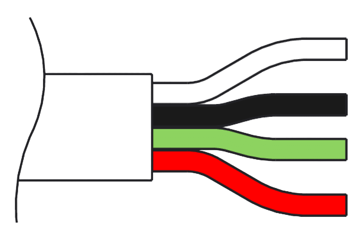
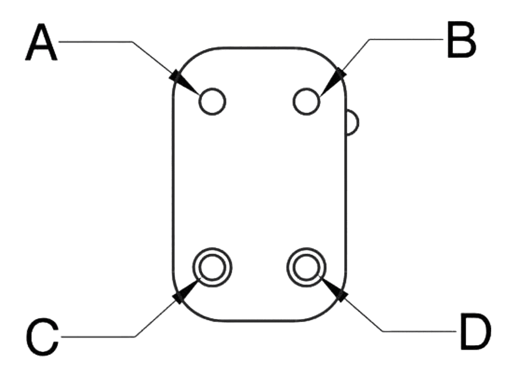
Please note pin orientation. Not to scale. Flying leads that terminate in bare wires do not have associated diagrams. In these cases, please refer to the wire color to determinate the correct pin out.

Type: Flying Lead (300 mm length)
Termination: Bare Wires

Wire Color

Function

Desc.

White

Supply 0 V

0 V

Black

Supply +

+24 V

Green

Input – (Ground Ref)

Differential Input Signal, –

Red

Input +

Differential Input Signal, +

Type: Case Mounted
Termination: Connector according to EN 175201-804/MIL 5015 equivalent, shell size 14

Pin

Function

Desc.

A

Supply +

+24 V

B

Supply 0 V

0 V

C

Output –
Enable Input

Output 0 V Reference
Drive Enable Input*

D

Input +

Differential Input, +

E

Input –

Differential Input, –

F

Output +

Output Signal

G

Earth

* When the enable function is selected, the function of pin C is the enable input. This replaces the standard pin function.

Type: Case Mounted
Termination: Connector according to EN 175201-804/MIL 5015 equivalent, shell size 14
Number of Contacts: 4

Pin

Function

Desc.

A

Supply +

+24 V

B

Input +

Differential Input, +

C

Input –

Differential Input, –

D

Supply 0 V

0 V

Type: Flying Lead
Termination: Winchester™ G4-20P

Pin

Function

Desc.

A

Supply 0 v

0 v

B

Supply +

+24 V

C

Input – (Ground Ref)

Differential Input, –

D

Input +

Differential Input, +

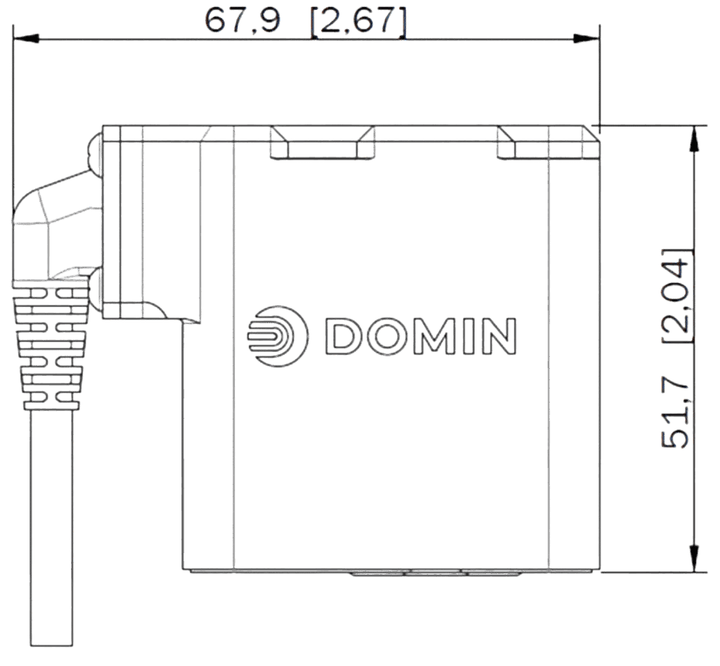
Unit Dimensions – Connector Code G and B4

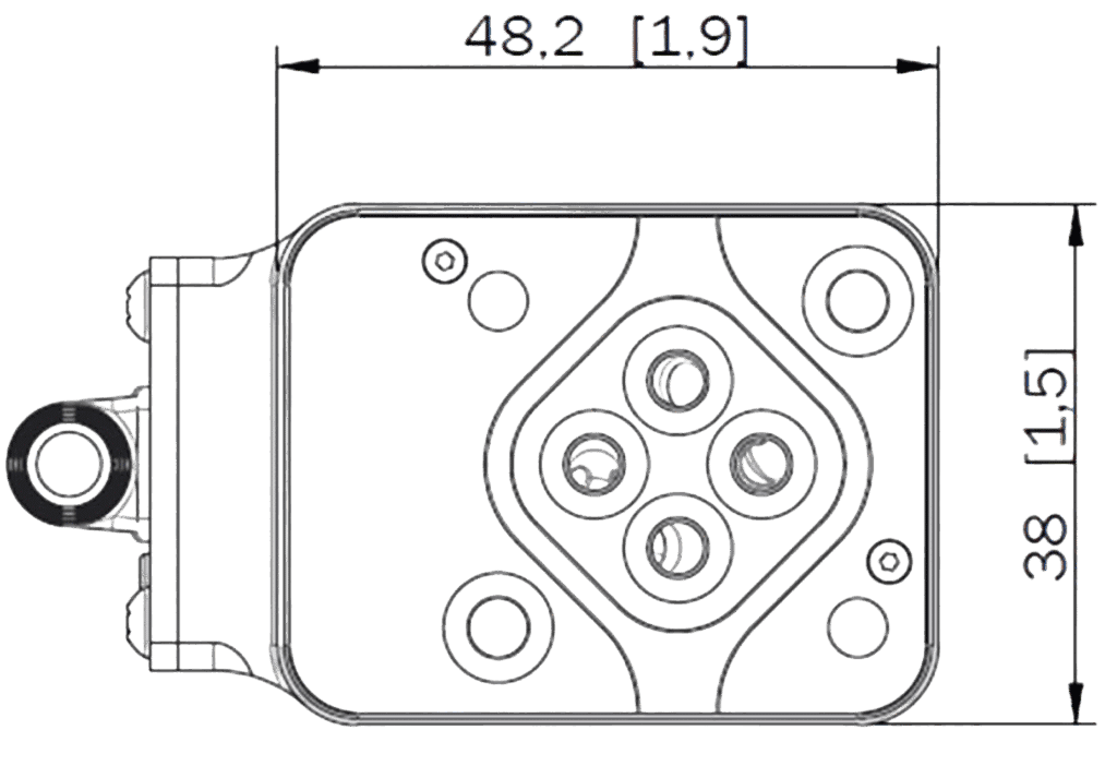
Unit Dimensions – Connector Code E and E4

Nominal dimensions are displayed in mm. Bracketed dimensions are in inches. Not to scale.

Mounting Surface Pattern Dimensions

Dia Ø
mm

X Position
mm

Y Position
mm

F1

M4

0

0

F2

M4

23.8

0

F3

M4

23.8

26.2

F4

M4

0

26.2

P

3.8

11.9

19.2

A

3.8

18.0

13.1

B

3.8

5.8

13.1

T

3.8

11.9

7.0

Bolts (F1, F2, F3, F4)

Type: M4 x 55 DIN EN ISO 4762-10.9
Required Torque: 2.5 Nm (5.53 ft-lbf)

O-Rings (P, A, B, T)

Type: 4.47 x Ø 1.78 (ISO 3601-1-008)
Material: NBR, EPDM or Viton, 70 Shore A
Hardness: 70 Shore A

Standards Compliance

EMC Regulations: EN 61000-6-2 / EN55011:1998+A1
Performance Tests: ISO 10770-1
Pressure Rating: EN 10771
Hydraulic Interface: ISO 10372-01-01-0-92

Not to scale.

Ordering Code

S4 Pro 1 2 3 4 5 6 7 8 9

Any value in range 0.5 to 18

Rate flow in l/min for 35 bar ∆P per control edge

R – Suffix for reversal of A and B port e.g. 18R

A

Axis cut (1% overlap linearized)

O

3% Overlap (linearized to 50% gain over center)

D

10% Overlap (with flow dead band)

X

For other options please enquire

A

± 10 V

B

± 20 mA

C

4 to 20 mA

D

± 5 V

E

± 5 mA

F

± 10 mA

G

± 50 mA

H

± 40 mA

I

± 25 mA

X

For other options please enquire

For differing input and output signals, use two letters,
e.g. AC denotes ± 10V input and 4 to 20 mA output

C

Center

X

For other options please enquire

B4

4 contact, unterminated flying lead

E

6 pin + PE circular connector*

E4

4 pin*

G

G4-20P Rack and Panel connector

X

For other options please enquire

* EN 175201-804/MIL 5015 equivalent connector, shell size 14

N

No enable functionality

Y

Enable mode on (Only available with connector option E)

R

Recommended – any hydraulic oil in accordance with DIN 51524, filtered in accordance with ISO4406 18/16/13. Compatibility with water-free synthetic fluids available on enquiry.

X

For other options please enquire

F

FFKM (Shore 75)

N

Nitrile (Shore 90)

V

Viton (Shore 85)

X

For other options please enquire

Assigned individually to any with customized options upon enquiry

Variants on Request

Domin is proud of their ability to offer tailored solutions that meet customers’ specific needs. If you require a non-standard configuration, or a bespoke modification, we are confident we can provide you with the best solution. Talk to us here and one of our team will respond as soon as possible.

Domin is a supplier and servo valve manufacturer for various applications including automotive/motorsports, aerospace, animatronics, simulation, robotics, and marine.