
Hydraulic Flow Dividers
Hydraulic flow dividers synchronize cylinders and motors. Gear flow dividers cover 95% of applications with errors as low as ±1.5–4%. Other options include flow divider valves (±4–5%), radial piston dividers (±0.5–0.8%), and volumetric dividers (zero error).

Flow rate: up to 58 gpm (219 lpm). Pressure up 4,600 psi (317 bar). Sync error: ±1.5 to ±4%. Available in 2 to 12 sections. Most popular model.
Flow rate: up to 145 gpm (548 lpm). Pressure up 3,500 psi (241 bar). Sync error: ±0.5 to ±0.8%. Available in 2 to 12 sections.
Flow rate: up to 79 gpm (298 lpm). Pressure up to 6,100 psi (420 bar). Sync error: nearly 0%. Available in 3 to 8 sections.
Flow rate: up to 39 gpm (150 lpm). Pressure up to 5,075 psi (349 bar). Sync error: ±4 to ±5%. Available in 2 sections only.
Flow Rate: 3.1 gpm (12 lpm). Pressure up to 3,045 psi (209 bar). Available in 2 sections only.
Need Support? We Can Help.
What Makes Us Different?
High Synchronization
Precise synchronization: Accuracy as low as ±0 to 0.5% error for applications needing high precision
Fast Shipping
Fast lead times: Fast and flexible shipping. Standard lead times of 4-6 weeks with expedited delivery in less than one week.
Greater Capabilities
Capable of handling bigger pressure differences between sections than other leading brands.
Flow Dividers 101
What are Flow Dividers?
When you have multiple motors or cylinders connected to one pump, they cannot operate simultaneously because power is not evenly distributed to each component. Flow dividers simplify this problem by splitting the flow from one source into two or more output parts, which can be equal or unequal.
Flow Divider Benefits
Common Designs
The most common designs include the gear-type and spool design. For applications requiring extremely high accuracy (greater than 99%), radial piston and volumetric designs work best.
Gear (2 to 12 sections): Gear flow dividers are a cost-effective way to divide flow without losing a large amount of energy or heat. Comparatively to spool dividers, these devices are more tolerant of contamination.
Spool (2 sections): This design relies on pressure compensation to divide flow and is limited to just two sections that can be split evenly, 50:50, or unequally. These are well-suited for applications where synchronization is flexible and complete accuracy is not a requirement.
Radial piston (2 to 12 sections): These are designed with high accuracy in mind, but have higher pressure drops than gear.
Volumetric (3 to 8 sections, 2 to 12 chambers): The volumetric design functions by volume dosage and the exchange between a volume synchronizer and working cylinders. The volumetric design is for high accuracy applications and has lower pressure drops compared to radial piston dividers.
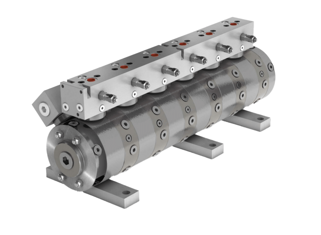
Radial Piston Flow Divider
How to Choose a Jahns Flow Divider
1. Main Specifications
First, identify the following parameters to match performance and sizing with system demands. This includes:
2. Determine Application Accuracy and Model
Next, determine how much accuracy is required.
While flow dividers are precision components, some degree of synchronization error is normal. In short-stroke applications (where the cylinder travels a limited distance per cycle), a small percentage of error is often negligible and unlikely to affect performance. However, in long-stroke applications, even a small percentage of synchronization error can accumulate across the full cylinder travel, potentially leading to misalignment, uneven load sharing, and increased mechanical stress.
Models Based on Accuracy
Gear flow dividers are the standard choice for general operations. For applications demanding higher precision, consider radial piston or volumetric dividers. Divider valves can be used for applications that allow lower accuracy.
Divider Valves
Only for 2 flows/sections. Compact, economical model. Accuracy between ±4–±5%.
Gear Flow Dividers
Most popular and cost-effective model. Accuracy between ±1.5–±4%.
Radial Piston Flow Dividers
Tighter tolerances than gear models with larger pressure drops, accuracy between ±0.5–0.8%. Input flow rates starting at 13 gpm (50 lpm).
Volumetric Flow Dividers
Highest precision model, designed for applications requiring near perfect accuracy (no error).
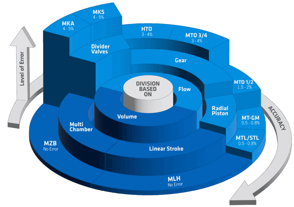
The chart below compares synchronization accuracy across different models of flow and volumetric dividers.
The first ring splits dividers into groups: flow (light blue) and volume (dark blue). The second ring shows the type of divider. Flow dividers options include divider valves, gear, and radial piston while volumetric dividers include multi-chamber and linear stroke designs. The outer ring lists specific series models with their synchronization error.
As you follow the chart clockwise, accuracy improves with the level of error decreasing. For example, the MKA and MKS divider valves have an error of 4–5%. The next model, HTO gear divider, has better accuracy with errors as low as 3-4%.
Technical Overview
Choose your flow divider series based on sections, flow, and pressure. Then, refine by synchronization accuracy.
|
Series |
Model |
Material |
Sections |
Flow Rate |
Pressure |
Sync Error |
|
Divider Valves |
MKA |
Aluminum |
2 |
0.53 up to 39 gpm |
3,045 psi (210 bar) |
±4 – 5% |
|
Divider Valves |
MKS |
Steel |
2 |
0.53 up to 39 gpm |
5,000 psi (350 bar) |
±4 – 5% |
|
Gear |
MTO |
Aluminum |
2 to 12 |
16 gpm (60 lpm) |
3,625 psi (249 bar) |
±1.5 – 2% |
|
Gear |
MTO |
Cast Iron |
2 to 12 |
58 gpm (219 lpm) |
3,900 psi |
±3 – 4% |
|
Gear |
HTO |
Cast Iron |
2 to 12 |
37 gpm (140 lpm) |
4,600 psi (317 bar) |
±3 – 4% |
|
Radial Piston |
MTL |
Steel |
2 to 12 |
66 gpm (249 lpm) |
3,500 psi (317 bar) |
±0.5 – 0.8% |
|
Radial Piston |
STL |
Steel |
2 to 12 |
105 gpm (397 lpm) |
3,500 psi |
±0.5 – 0.8% |
|
Radial Piston |
MT-GM |
Steel |
2 to 12 |
145 gpm (548 lpm) |
3,500 psi |
±0.5 – 0.8% |
|
Volumetric |
MLH |
Steel |
3 to 8 |
50 cm³ up to 12,300 cm³ (3.1 in³ up to 750.6 in³) |
3,600 psi |
No sync error |
|
Volumetric |
MZB |
Steel |
2 to 12 |
79 cm³ up to 40,000 cm³ (4.8 in³ up to 2440.9 in³) |
3,600 psi (241 bar) or for special builds 6,100 psi (420 bar) |
No sync error |
Application Examples and Solutions
Some common applications include synchronizing fluid motors and hydraulic cylinders, and intensifying pressure in hydraulic pumps. Our flow dividers are available with or without pressure relief valves to protect hydraulic systems from excessively high pressures.
Synchronization
In the case where multiple cylinders need to move something in sync, flow dividers offer a great solution. This is useful, for example, in lifting platforms, where the platform must remain level to prevent binding in the guiding mechanisms as well as for the objects on top of the platform.
Pressure Multiplication
Flow dividers can be utilized as a pressure multiplier. This type of hydraulic circuit can be used where a low-pressure circuit is already in use and where there is only need of high-pressure flow.
Hydraulic Driving
This is achieved by adding an extra section of equal or greater displacement to the flow divider. The return line of this section is connected directly to tank so that it in effect works as a motor for the other sections thereby increasing their outlet pressures.