With this new generation of Universal Hydraulik LKM oil-coolers, cooling performance has been improved. These coolers are ideally suited for mobile installations – for the cooling of hydraulic or lubricating oils. In order to make the cooler range as comprehensive as possible, the smaller models are also available as single or dual versions, thus covering oil-cooling requirements for both low and high oil throughflow volumes.
Product Features
Testing pressure: 363 psi (25 bar) static according to DIN 50104
Operating pressure: 232 psi (16 bar) (min. 2 Mill. Cycles from 0-232 psi (0-16 bar) at 2 Hz and 140°F (60 °C)
Compact oil-cooler
High cooling performance
Low pressure loss
Low noise level
High flexibility
Also for use with water/glycol
Options:
Variable motor; Hydro / 400V
Filter pad available on request
Thermo-bypass
Thermo-switch
Seawater version also available
Universal Hydraulik is a supplier and heat exchanger manufacturer for various applications including construction, mechanical, marine, and industrial.
Bare tube heat exchangers are an ideal choice for cooling high viscosity fluids and particle containing fluids that may clog a cooler with internal cooling fins.
Fail-safe coolers prevent the mixture of fluids should one of the cooling tubes fail. This is achieved by double wall tubes and safety switches that indicate a tube failure.
Hybrid heat exchangers combine the advantages of shell & tube and plate heat exchangers. The larger surface area permits a physically smaller heat exchanger with better cooling capacity.
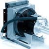
With this new generation of Universal Hydraulik LKI oil-coolers, noise level has been reduced. These coolers are ideally suited for mobile installations – for the cooling of hydraulic or lubricating oils. The housings have been optimized, in order to produce the very low noise level and to make the cooler range as comprehensive as possible. The smaller models are also available as single or dual versions, thus covering oil-cooling requirements for both low and high oil through-flow volumes.
Product Features
Testing pressure: 363 psi (25 bar) static according to DIN 50104
Operating pressure: 232 psi (16 bar) (min. 2 Mill. Cycles from 0-232 psi (0-16 bar) at 2 Hz and 140 °F (60 °C))
Bare tube heat exchangers are an ideal choice for cooling high viscosity fluids and particle containing fluids that may clog a cooler with internal cooling fins.
Fail-safe coolers prevent the mixture of fluids should one of the cooling tubes fail. This is achieved by double wall tubes and safety switches that indicate a tube failure.
Hybrid heat exchangers combine the advantages of shell & tube and plate heat exchangers. The larger surface area permits a physically smaller heat exchanger with better cooling capacity.
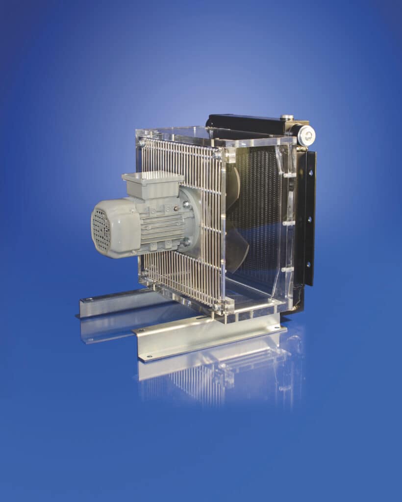
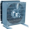
Universal Hydraulik LKI oil-air coolers, the manufacturers have succeeded in reducing the noise level. These coolers are ideally suited for stationary installations – for the cooling of hydraulic or lubricating oils. The range has been extended to include slow-running ventilators, and the housings have been optimized, in order to produce the very low noise level. In order to make the cooler range as comprehensive as possible, the smaller models are also available as single or dual versions, thus covering oil cooling requirements for both low and high oil throughflow volumes.
Product Features
Testing pressure: 363 psi (25 bar) static according to DIN 50104
Operating pressure: 232 psi (16 bar) (min. 2 Mill. Cycles from 0-232 psi (0-16 bar) at 2 Hz and 140 °F (60 °C))
Compact oil-cooler
High cooling performance
Low pressure loss
Max. operating temperature: 248 °F (120 °C)
High flexibility
2″ SAE flange from LKI 700 upward
Cooling of: Oil, HFA, HFB, HFC, HFDfluidsup to v = 100 x 10 – 6 m2/s,water/glycol min. 65:35 – under no circumstances water without corrosion prevention
Coolant: air
Variable motor; Hydro / 12/24V
Options:
Testing pressure 580 psi (40 bar)
Filter pad available on request
Thermo-bypass
Thermal-switch
Atex certification (II 2GD IIC T4 X) according to 94/9/EGS
Stainless steel
Universal Hydraulik is a supplier and heat exchanger manufacturer for various applications including construction, mechanical, marine, and industrial.
Bare tube heat exchangers are an ideal choice for cooling high viscosity fluids and particle containing fluids that may clog a cooler with internal cooling fins.
Fail-safe coolers prevent the mixture of fluids should one of the cooling tubes fail. This is achieved by double wall tubes and safety switches that indicate a tube failure.
Hybrid heat exchangers combine the advantages of shell & tube and plate heat exchangers. The larger surface area permits a physically smaller heat exchanger with better cooling capacity.
Universal Hydraulik TL plate heat exchangers consist of a number of corrugated plates. The plate pack is mounted between a fixed and a movable pressure plate, positioned by an upper and a lower carrying bar, and compressed by several tightening bolts. Gasketed type plates and welded modules with various patterns are available for a wide range of applications. The media can pass the heat exchanger either in cocurrent or counter-current flow. Depending on the operating conditions media and temperature-resistent gaskets of the glued on or clipped on version are used. The welded plate module forms are hermetically sealed flow channel to the outside. The transition from one module to another is sealed by a ring gasket made of a special material.
Product Features
Compact design, low space requirements, low weight
Modular system offers high degree of flexibility, capacity adjustment by adding or removing plates
Easy to clean
High specific thermal efficiency suitable for low temperature differences
Excellent fouling resistance due to high turbulence and smooth surfaces
Options:
Various plate materials (titan, Hastelloy, etc.)
Module welded plates
Variable depths of stamping
Increased plate thickness
Universal Hydraulik is a supplier and heat exchanger manufacturer for various applications including construction, mechanical, marine, and industrial.
Bare tube heat exchangers are an ideal choice for cooling high viscosity fluids and particle containing fluids that may clog a cooler with internal cooling fins.
Fail-safe coolers prevent the mixture of fluids should one of the cooling tubes fail. This is achieved by double wall tubes and safety switches that indicate a tube failure.
Hybrid heat exchangers combine the advantages of shell & tube and plate heat exchangers. The larger surface area permits a physically smaller heat exchanger with better cooling capacity.
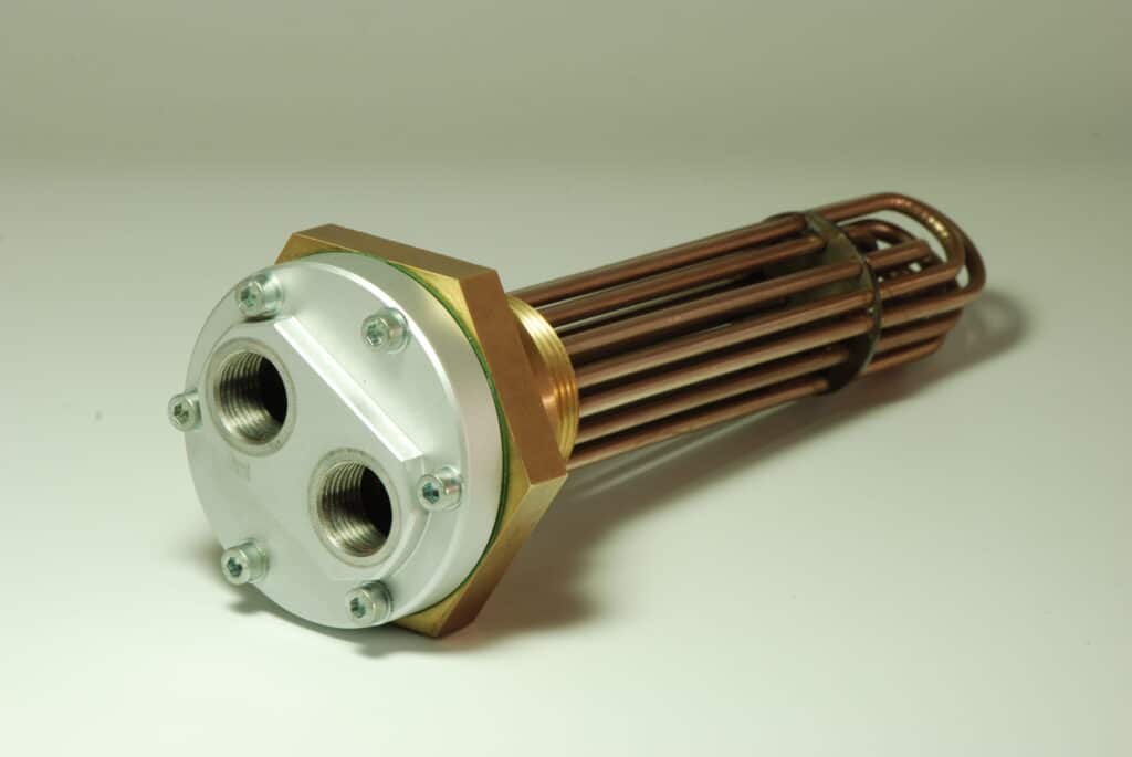
The Universal Hydraulik UKC-G series has been developed for the installation in oil tanks or gear boxes. This heat exchanger can be simply installed to existing screw threads for tank heaters.
Product Features
Available in 17 sizes
Cooling surfaces from 0,15 to 0,43 m2 and screw thread sizes of 1.5″and 2″
Easy assembly in existing screw threads for tank heaters
Inexpensive, space saving solution
End cap: G 1/2″ Water connection
Cooling efficiency depending on circulation of cooling tubes in tank or gear box
Extremely compact
Max. pressure of 145 psi (10 bar) and max. temperature of 203°F (95°C)
Options:
Special lengths on request
Hard foam isolation
Studs and threaded bushing for mounting
Mounting feed and transport hooks
Nickel brazed version
Shipment:
Cooler with end cap, screws, and washer
Universal Hydraulik is a supplier and heat exchanger manufacturer for various applications including construction, mechanical, marine, and industrial.
Bare tube heat exchangers are an ideal choice for cooling high viscosity fluids and particle containing fluids that may clog a cooler with internal cooling fins.
Fail-safe coolers prevent the mixture of fluids should one of the cooling tubes fail. This is achieved by double wall tubes and safety switches that indicate a tube failure.
Hybrid heat exchangers combine the advantages of shell & tube and plate heat exchangers. The larger surface area permits a physically smaller heat exchanger with better cooling capacity.
The Fail-Safe Safety Heat Exchanger from Universal Hydraulik is satisfying the highest quality demands for decades. Since then, it is avoiding application errors and the unintended mixing of two fluids.
The SCM/FS failsafe series is based on the successful SCM series of hybrid coolers. This brings all the benefits of the high-efficiency hybrid coolers to the failsafe series. A further enhancement of this series is that no accumulator is required. Leakage is monitored 100% by an electronic sensor which sends out a signal should leakage occur in either the inner or outer tube.
The 100% electronic monitoring is suitable for all Industry 4.0 applications. Safety Heat Exchanger is used for applications where an error could lead to serious consequences.
Standard Version
Version with/for double pipes
100% electronic monitoring
Leak detector on request with ATEX Certificate
Removable sealing cover for cleaning internal water pipes
Optional:
Seawater version
Marine certificates
Offshore approvals
Hydro-test
1 material certificate
Customized solutions
Internal by-pass valve
SAE/ANSI flanges
For detailed product information, please see our catalog.
Universal Hydraulik is a supplier and heat exchanger manufacturer for various applications including construction, mechanical, marine, and industrial.
Bare tube heat exchangers are an ideal choice for cooling high viscosity fluids and particle containing fluids that may clog a cooler with internal cooling fins.
Hybrid heat exchangers combine the advantages of shell & tube and plate heat exchangers. The larger surface area permits a physically smaller heat exchanger with better cooling capacity.
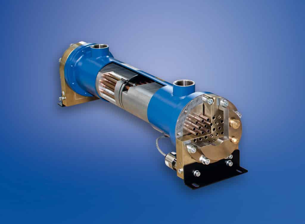
Depending on the customer’s application, a bare tube shell & tube heat exchanger from Universal Hydraulik is the better choice. High viscosities, or fluids with small particles, may clog the fins used for the hybrid-design.
CKM-bare tube heat exchanger
With the same quality, Universal Hydraulik is manufacturing bare tube heat exchanger for the past several years. We can assist you with the decision if either a space-saving hybrid or a classic bare tube heat exchanger is the best for your application.
Product Features:
Water side: optimized durability due to water tubes
Small or large water tubes
On-tank cooler
Heat dissipation up to 1,200 HP (900 kW)
Flow rates up to 528 gym (2000 l/min)
Copper, Copper-Nickel, or Stainless Steel tubes
Options:
Seawater version
Marine certificates
Offshore approvals
Hydro-test
1 material certificate
Customized solutions
Complete stainless steel cooler
Compressed air application
Water-water application
Internal by-pass valve
SAE/ANSI flanges
Universal Hydraulik is a supplier and heat exchanger manufacturer for various applications including construction, mechanical, marine, and industrial.
Hybrid heat exchangers combine the advantages of shell & tube and plate heat exchangers. The larger surface area permits a physically smaller heat exchanger with better cooling capacity.
Fail-safe coolers prevent the mixture of fluids should one of the cooling tubes fail. This is achieved by double wall tubes and safety switches that indicate a tube failure.
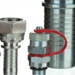
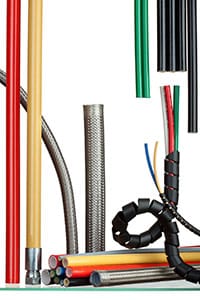
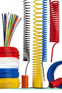
ZEC offers Low Pressure Theromplastic Hoses, for applications in the pneumatics field and in lubrication. They are manufactured in the various typologies in single, multiple or spiral version, in Rilsan PA11, Polyamide 12, Polyurethane, Hytrel, Polyethylene, Ptfe. ZEC hoses meet the main international regulations.
Product Features:
Reduced weight and size thanks to the use of raw materials of improved toughness and low specific weight Excellent resistance to fatigue stress, alternating flexing and vibrations Due to the low surface roughness of approximately 0.6 microns, Zec’s thermoplastic hoses achieve minimal head loss and increased flow rates Extremely long lifespan thanks to the exceptional anti-aging qualities of the techno polymers used
Rilsan® Tubes:
ZEC Rilsan® tubes are in compliance with the European directives REACH (2006/1907/EC) and RoHS 2 (2011/65/EU).
Rilsan® HT Tube – new:
For all the applications that require thermoplastic flexible tubes for high working temperature ZEC RILSAN® HT provides a valid alternative to the traditional metal or PTFE tubing. ZEC RILSAN® HT is a thermoplastic tubing suitable for conveying hot fluids not water-based, and it is used in industrial and automotive field. The raw material used in this tubing is the Rilsan® HT, a special PolyPthalAmide (PPA) obtained from renewable sources. It is characterized by excellent chemical and mechanical properties, and a high resistance to the thermo-oxydative heat aging. This tubing has successfully passed all tests required by the DIN 73378 and ISO 76281 international standards.
Product Features:
ZEC RILSAN® HT thermoplastic tubes are an innovative solution for the industrial or automotive applications that require resistance to high temperatures, as alternative to the traditional metal or PTFE tubes. ZEC RILSAN® HT tube is suitable for conveying hot fluids (oils, fuels, air and refrigerant fluids) not water-based. ZEC RILSAN® HT tubes have been developed using an innovative thermoplastic Bio-polymer called Rilsan® HT obtained from renewable sources. It is a PolyPhtalAmide (PPA) characterized by an excellent resistance to the thermo-oxydative heat aging. This material is Biobased up to 70% (see Fig. 1) and it favors the emissions reduction of carbon dioxide (CO2). ZEC RILSAN® HT tube provides excellent thermoforming, good mechanical properties and abrasion resistance, together with a high resistance to chemicals and to aggressive environments. This tubing has successfully passed all tests required by the DIN 73378 and ISO 7628 international standards. Working temperature of ZEC RILSAN® HT tubes is in the range -40°C to +150°C. For temperatures above ambient (23°C), it is necessary to calculate the corrected burst pressure using the correction factor obtained by means of diagram in Fig. 2.
Rilsan® T Tube:
ZEC RILSAN® T is a thermoplastic tubing particularly suitable for industrial pneumatics and developed using an innovative polymer: the Rilsan® T. Such raw material is a special PolyAmide (PA10.10) of green origin, obtained from renewable sources, alternative to technical polymers derived from hydrocarbons. ZEC RILSAN® T is a high quality tubing able to ensure excellent resistance to pressure, great flexibility and reduced bend radii. For all applications for fluids conveying, ZEC RILSAN® T tube also shows an excellent chemical resistance and a good resistance to heat. This tubing has successfully passed all tests required by the DIN 74324, DIN 73378 and ISO 76281 international standards.
Product Features:
ZEC RILSAN® T tubes are particularly suitable for industrial pneumatics, compressed air circuits and oil transfer. These tubing have been developed using an innovative thermoplastic polymer, the Rilsan® T, a special BIO-PolyAmide (PA10.10) obtained from green renewable sources (see Fig. 1). This material provides an effective alternative to technical polymers derived from hydrocarbons and it favors the emissions reduction of carbon dioxide (CO2). ZEC RILSAN® T tube provides excellent physical and mechanical properties, together with a good chemical resistance even with polyols, solvents, paints and compatible gas, in chemically aggressive environments. This tubing has successfully passed all tests required by the DIN 74324, DIN 73378 and ISO 7628 international standards. Working temperature of ZEC RILSAN® T tubes is in the range -40°C to +100°C. For temperatures above ambient (23°C), it is necessary to calculate the corrected burst pressure using the correction factor obtained by means of diagram in Fig. 2.
Rilsan® HTR Tube:
ZEC HTR thermoplastic tube is widely used for years in industrial automation. This is a high quality product ideal for pneumatic applications, where it is required great reliability, good mechanical resistance and reduced bend radii. The use of a special Thermoplastic Polyester Elastomer (TPE or TEEE) allows to achieve an excellent compromise between features of flexibility and resistance to pressure.
Product Features:
ZEC HTR tubes are particularly suitable for industrial pneumatics, compressed air circuits and oil transfer. Unlike traditional tubes made of thermoplastic flexible grade material, available on market today, ZEC HTR tubes do not contain plasticizers because the flexibility is guaranteed by their internal elastomeric molecular structure. Therefore, these tubes do not have the inconvenience of contamination by release of plasticizer resulting in tube stiffening. Unlike traditional tubes made of thermoplastic flexible grade material, available on market today, ZEC HTR tubes do not contain plasticizers because the flexibility is guaranteed by their internal elastomeric molecular structure. Therefore, these tubes do not have the inconvenience of contamination by release of plasticizer resulting in tube stiffening. At room temperature chemical resistance is good also with polar fluids, glycols, higher molecular weight alcohols, weak acids and bases. Working temperature of ZEC HTR tubes is in the range -40°C to +100°C. For temperatures above ambient (23°C), it is necessary to calculate the corrected burst pressure using the correction factor obtained by means of diagram in Fig.1.
ZEC is a supplier and thermoplastic tubing and hoses manufacturer for various applications including construction, mechanical, technological, and industrial.
A wide variety of thermoplastic hose materials such as Rilsan PA11, Polyamide 12, Polyurethane, Hytrel, Polyethylene, and Ptfe are available to suit your low-pressure application
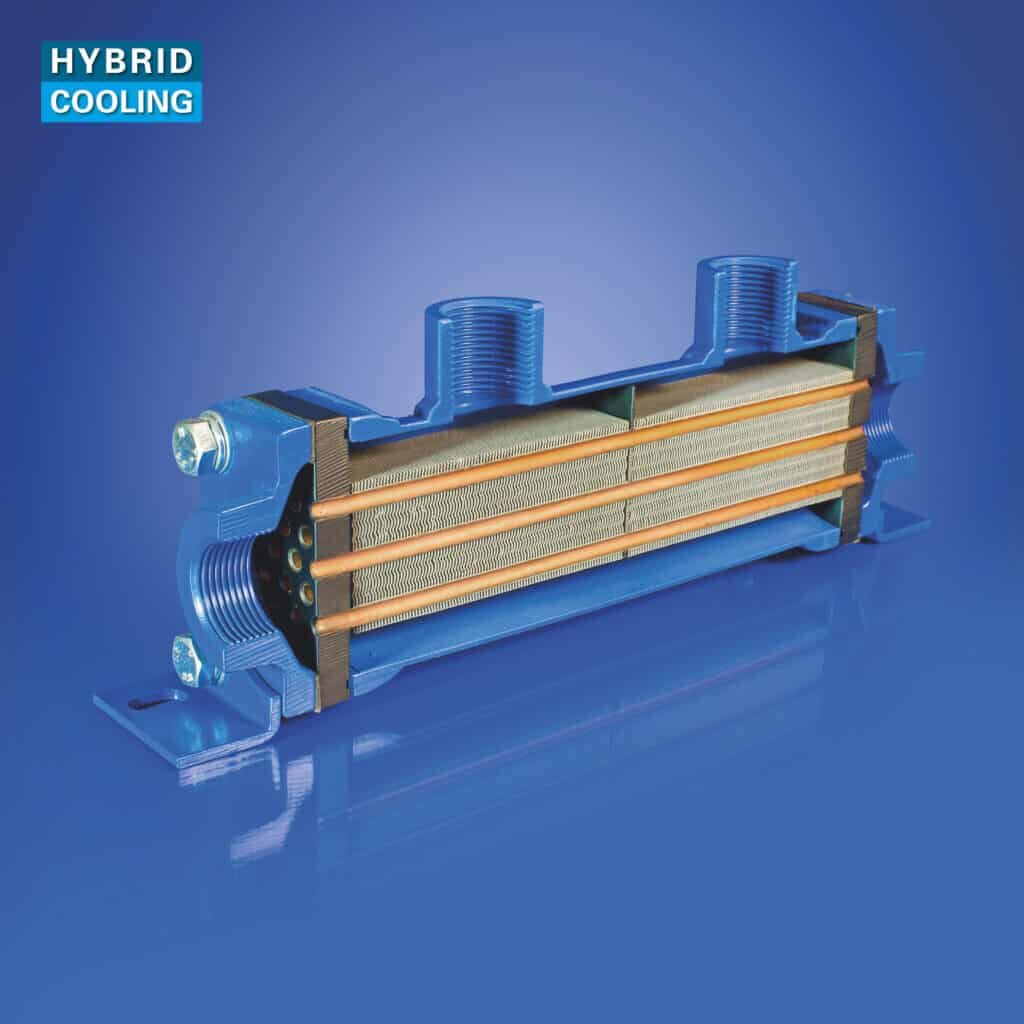
The Hybrid Heat Exchanger produced by Universal Hydraulik combines the advantages of Shell & Tube- and Plate Heat Exchangers. A larger cooling surface through the hybrid-design and the easy to clean waterside allows us to manufacture heat exchangers in a smaller size with a better cooling capacity.
Product Features:
Aluminum fins ensure larger levels of heat exchange
Heat dissipation up to 6,700 HP (5,000 kW)
Oil flow rates of up to 581 gal/min (2,200 l/min)
Removable end caps for easy cleaning of the tubes
Flanges allow the heat exchangers to be turned through 90°
Bare tube heat exchangers are an ideal choice for cooling high viscosity fluids and particle containing fluids that may clog a cooler with internal cooling fins.
Fail-safe coolers prevent the mixture of fluids should one of the cooling tubes fail. This is achieved by double wall tubes and safety switches that indicate a tube failure.