
Hydraulic Pressure Intensifiers
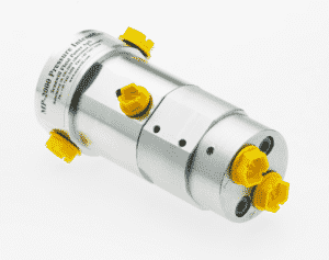
Compact yet powerful, pressure intensifiers deliver a nearly instant pressure boost precisely when and where it’s required. Low to medium to high pressure solutions. Intensification ratios up to 16 times. Maximum outlet pressures of 58,000 psi (4,000 bar).

Low/Medium Pressure (up to 800 bar / 11,200 psi)
High Pressure
(up to 4,000 bar / 58,000 psi)
Hydraulic Intensifier Accessories
Need Support? We Can Help.
What Makes Us Different?

Easily add pressure to existing systems
Increase output pressure from a low-pressure supply without major investments or upgrades.

Increase energy savings for the entire system
Add pressure only where and when needed. Using low-pressure components with an intensifier cuts down on operating costs.
Fast lead times of 1 to 2 weeks
1-2 week lead times, so that you can work faster. For cases with higher urgency, faster delivery may be possible.
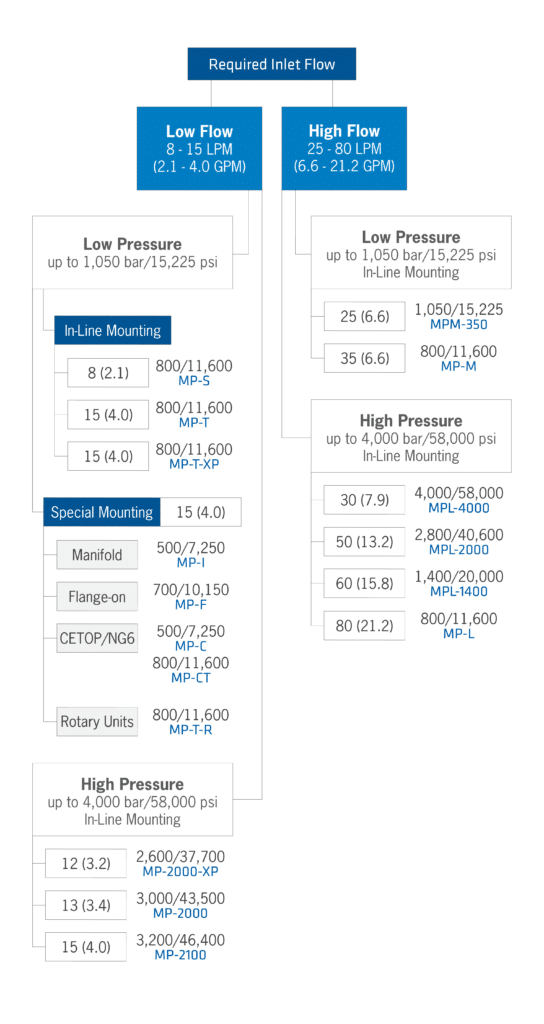
How to Select a Model
To select a model, it is recommended to start with the most common series, the MP-T. The MP-T has a pressure rating of 20-800 bar/290-11,600 psi with a flow rate up to 15 LMP/4.0 gpm. The MP-T is mounted as an in-line pressure intensifier.
The primary differences between models involve the need for additional flow, specialized mounting, or unique application requirements.

How to Select a Pressure Intensifier Guide
Pressure intensifiers are selected by choosing the intensification ratio (the multiplication factor from your input pressure to your required output pressure), flow rate, pressure, and mounting requirements for your applications.
1. Determine intensification ratio (psi)
Pressure intensifiers can provide standard intensification ratios of up to 16 and yield maximum outlet pressures of 58,000psi/4,000 bar. To determine the intensification ratio, first divide the desired outlet pressure by the inlet pressure.
2. Determine flow rate (gpm)
Next, determine the flow rate. Depending on the model, hydraulic intensifiers can have a flow rate starting at 0.3 gpm/1.1 lpm and up to 21 gpm/79.4 lpm.
3. Select mounting
Pressure intensifiers can be mounted in several configurations including in-line, flange-on, manifold, cartridge type, and CETOP mounting.
4. Determine how to plumb return line
Once the pressure intensification is reached, it is necessary to determine how the return flow will be plumbed. There are two versions. For plumbing around the intensifier, an S-Version is required. To allow the return flow from the component to pass through the intensifier, a P-Version is needed. The P-Version includes a POV valve integrated into the intensifier. In high flow applications, restricting the flow is necessary to prevent damage to the intensifier. This can be achieved by adding a flow control and a P.O. check valve to prevent excess flow.
5. Select intensifier
With the previous information gathered, an intensifier can be selected with a code.
How to Select a Pressure Intensifier Example
Pressure intensifiers are selected by choosing the intensification ratio (the multiplication factor from your input pressure to your required output pressure), flow rate, pressure, and mounting requirements for your applications.
1. Determine intensification ratio (psi)
Pressure intensifiers can provide standard intensification ratios of up to 16 and yield maximum outlet pressures of 58,000psi/4,000 bar. To determine the intensification ratio, first divide the desired outlet pressure by the inlet pressure.
2. Determine flow rate (gpm)
Next, determine the flow rate. Depending on the model, hydraulic intensifiers can have a flow rate starting at 0.3 gpm/1.1 lpm and up to 21 gpm/79.4 lpm.
3. Select mounting
Pressure intensifiers can be mounted in several configurations including in-line, flange-on, manifold, cartridge type, and CETOP mounting.
4. Determine how to plumb return line
Once the pressure intensification is reached, it is necessary to determine how the return flow will be plumbed. There are two versions. For plumbing around the intensifier, an S-Version is required. To allow the return flow from the component to pass through the intensifier, a P-Version is needed. The P-Version includes a POV valve integrated into the intensifier. In high flow applications, restricting the flow is necessary to prevent damage to the intensifier. This can be achieved by adding a flow control and a P.O. check valve to prevent excess flow.
5. Select intensifier
With the previous information gathered, an intensifier can be selected with a code.