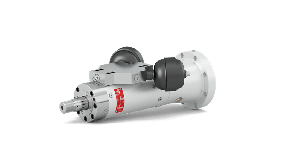
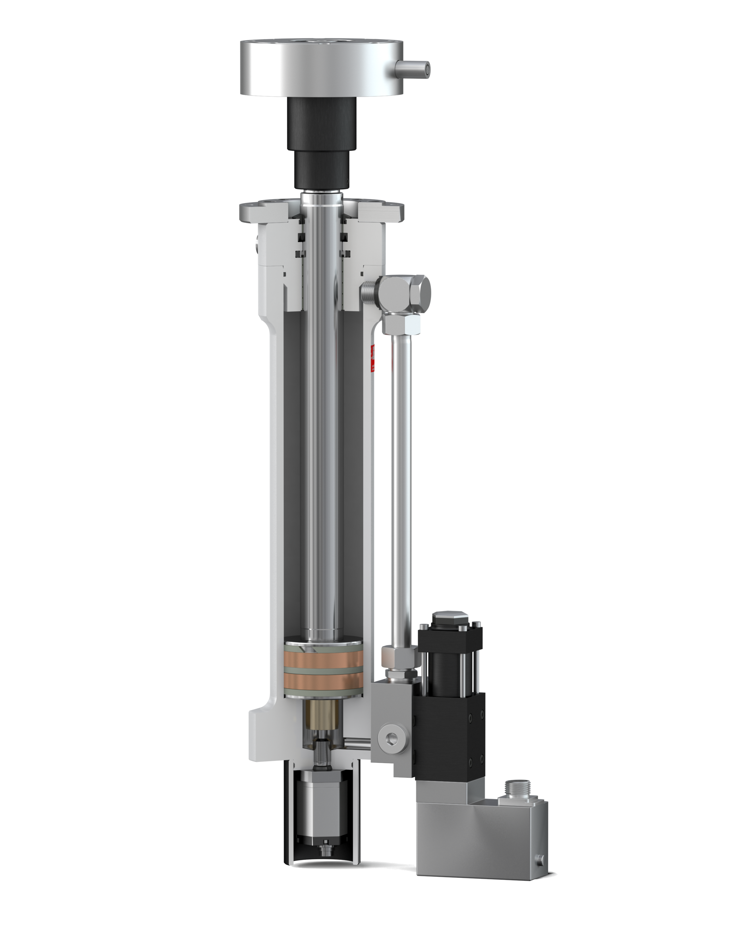
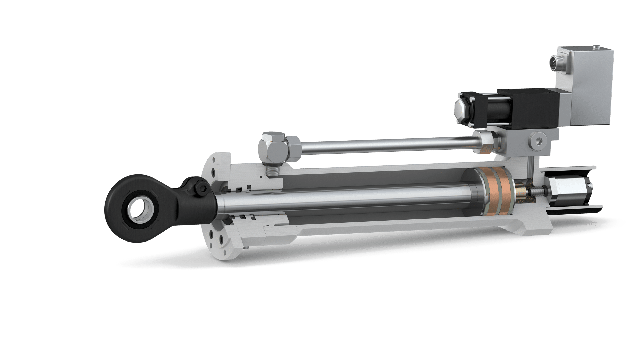
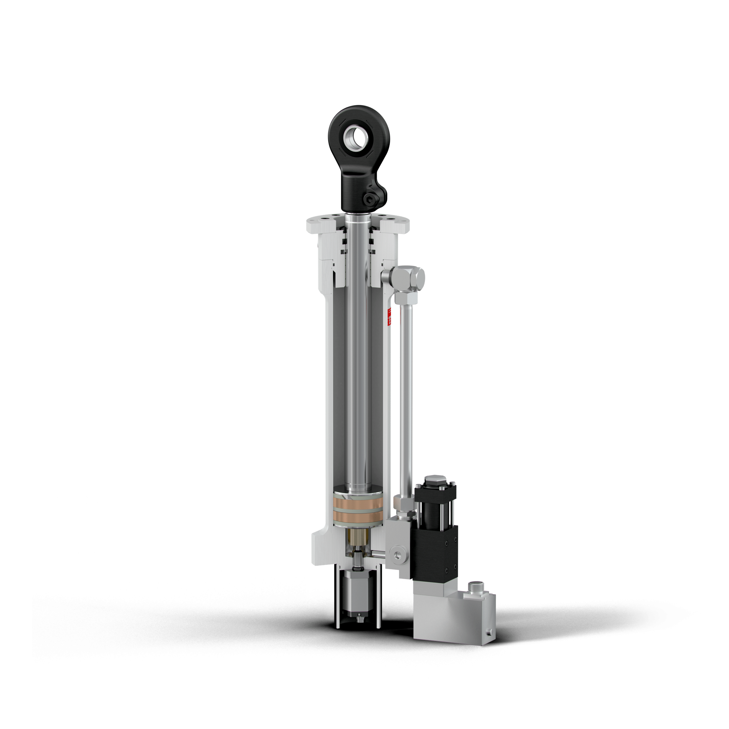
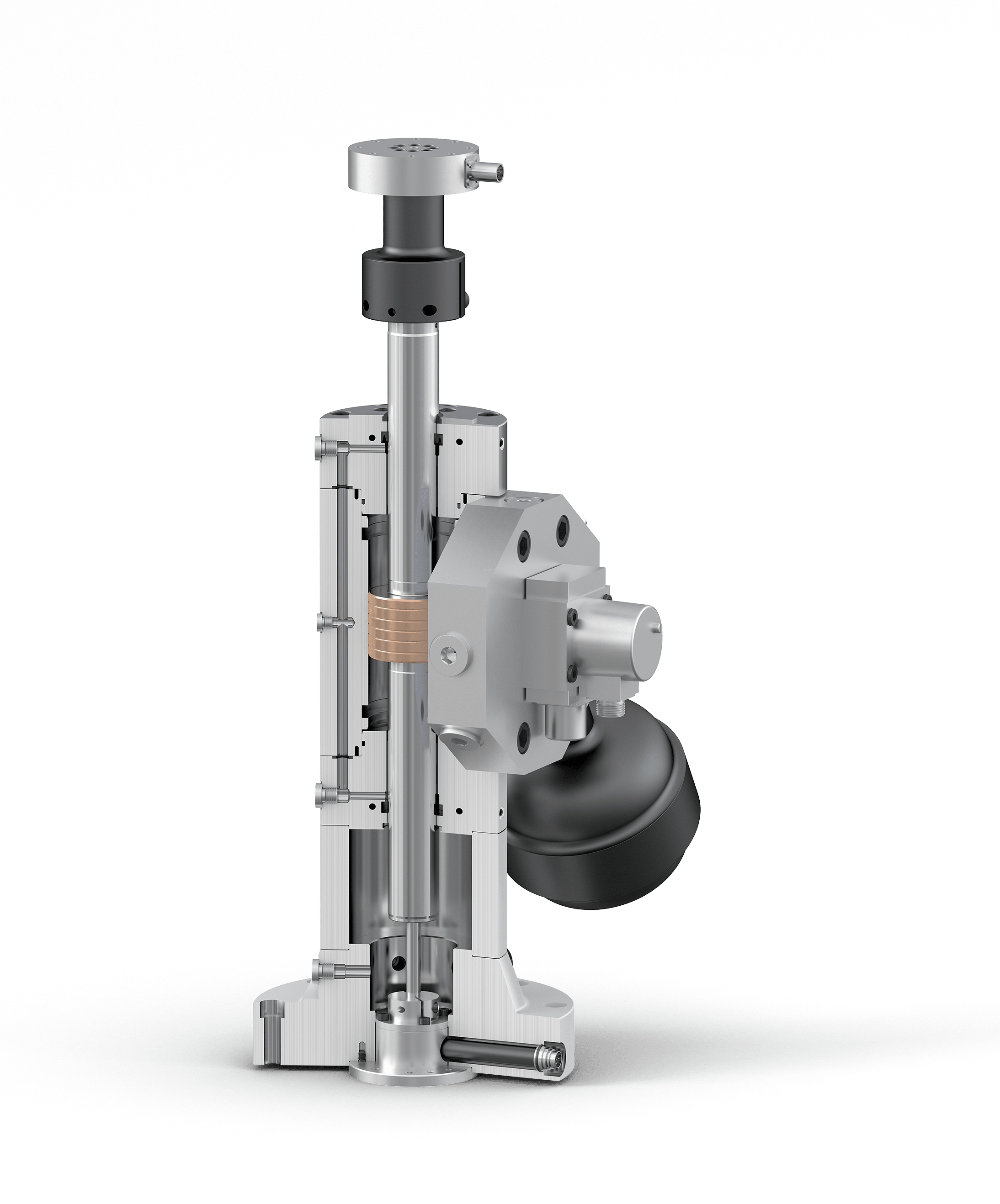
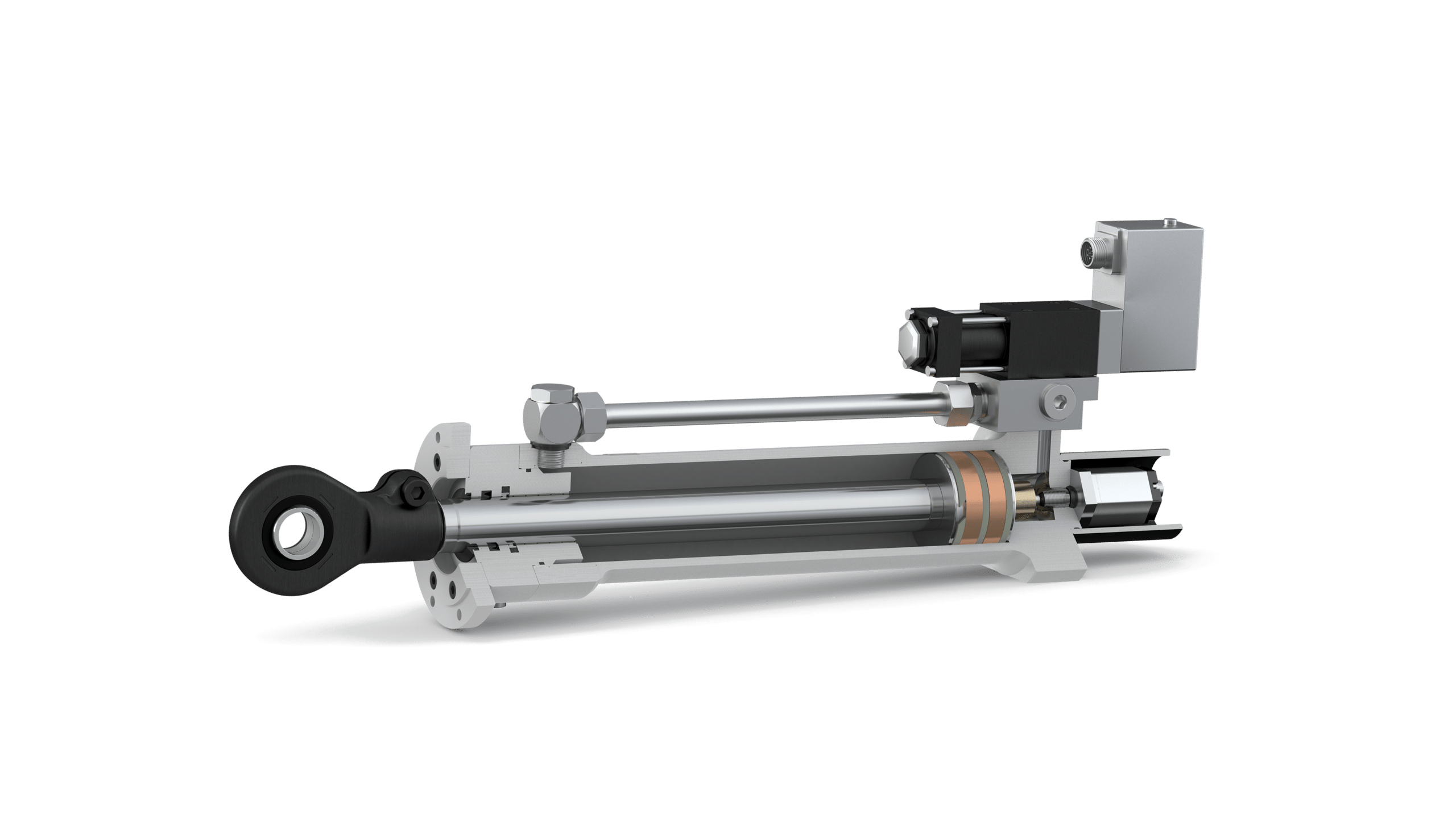
The Hänchen Ratio-Clamp® keeps the position for you. This device is a positive rod clamping safety device. The Ratio-Clamp is unlocked by hydraulic pressure. In the event of an electrical/hydraulic power loss, the potential energy of the internal Bellville washers load a conical piston, driving it over the friction fingers resulting in securing the load. “A true self contained safety clamp.”
Wherever power failures or malfunctions pose a risk to the safety of people or machinery, the rod locking device is there to save the day. It is also useful to accurately hold the cylinder rod in an exact position without the need to keep hydraulic pressure on the cylinder, thereby saving energy while maintaining accuracy. It clamps down and fixes the piston rod right where it is with no additional power needed.
Advantages of hydraulic rod locks
No axial rod movement during clamping and releasing
Protective clamping effect in case of a power failure
Load capacity that is independent of direction
Clamps completely surrounding rods
IoT 4.0 Compatible: Integrated sensors to know if the clamp is locked or unlocked
Boasting a retention force of up to 101,000 lbf., the clamp hydraulically holds the piston rod in whatever position it is in at that particular moment without having to generate extra power (no extra energy) for an unlimited period of time. The clamping device Ratio-Clamp is approved by the German Technical Inspection Agency (TÜV).
Special development of Custom solutions (larger rod diameters, intermediate size, greater clamping forces) pose no problem for the Hänchen specialists. Hänchen is particularly proud of its RC-H model. Following a request from the Health and Safety Centre of the Employers’ Liability Association (BGZ iron and metal section III, Düsseldorf), Hänchen developed the new safety clamping hydraulic Ratio-Clamp under extreme conditions for use with hydraulic presses and injection molding machines.
Comparison of Fixation Options for Round Rods
Electronic Control
Port Lock-Off
Pivot Pin Locking
Clamping Unit Ratio-Clamp®
Energy Efficient
–
+
+
+
Position Accuracy
+
–
+
+
Independence from external influences
+
–
+
+
Effort
–
+
–
+
Flexible positioning
+
+
–
+
Technical Data
Releasing Pressure
Locking
Sealing System
Certification
Ratio-Clamp
Basic design
Reduced design
Basic design
Basic design
Ratio-Clamp (Reduced Releasing Pressure)
With spring power
With spring power
With spring power
With spring power
Ratio-Clamp (Pressure Piston Seal)
Servocop®
Servocop®
Pressure Piston Seal
Servocop®
Ratio-Clamp (As a Safety Component)
TÜV
TÜV
TÜV
TÜV, DGUV Test
Rod Ø (in) | [mm]
Max. Holding Load (lbf) | [kN]
Releasing Pressure Min. (psi) | [bar]
0.630 [16]
2248 [10]
870 [60]
0.709 [18]
2810 [12.5]
797 [55]
0.787 [20]
3147 [14]
797 [55]
0.866 [22]
3821 [17]
1015 [70]
0.984 [25]
4496 [20]
1015 [70]
1.102 [28]
7082 [31.5]
1305 [90]
1.181 [30]
8992 [40]
1522 [105]
1.260 [32]
8992 [40]
870 [60]
1.417 [36]
10124 [45]
1087 [75]
1.575 [40]
11240 [50]
1160 [80]
1.772 [45]
14612 [65]
1015 [70]
1.969 [50]
17984 [80]
1305 [90]
2.205 [56]
20232 [90]
1087 [75]
2.362 [60]
22480 [100]
1087 [75]
2.480 [63]
22480 [100]
1232 [85]
2.756 [70]
31473 [140]
1160 [80]
3.150 [80]
40465 [180]
1305 [90]
3.543 [90]
44961 [200]
942 [65]
3.937 [100]
56201 [250]
1087 [75]
4.331 [110]
67442 [300]
942 [65]
4.724 [120]
74186 [330]
1015 [70]
4.921 [125]
78783 [350]
1087 [75]
5.512 [140]
101164 [450]
942 [65]
Rod Ø (in) | [mm]
Max. Holding Load (lbf) | [kN]
Releasing Pressure Min. (psi) | [bar]
0.630 [16]
1798 [8]
725 [50]
0.709 [18]
1798 [8]
507 [30]
0.787 [20]
2023 [9]
580 [40]
0.866 [22]
2697 [12]
652 [45]
0.984 [25]
3372 [15]
725 [50]
1.102 [28]
5620 [25]
942 [65]
1.181 [30]
6744 [30]
1087 [75]
1.260 [32]
6744 [30]
652 [45]
1.417 [36]
7193 [32]
725 [50]
1.575 [40]
8542 [38]
797 [55]
1.772 [45]
10116 [45]
725 [50]
1.969 [50]
12364 [55]
870 [60]
2.205 [56]
13488 [60]
725 [50]
2.362 [60]
15736 [70]
797 [55]
2.480 [63]
13488 [60]
797 [55]
2.756 [70]
22480 [100]
797 [55]
3.150 [80]
29225 [130]
942 [65]
Rod Ø (in) | [mm]
Max. Holding Load (lbf) | [kN]
Releasing Pressure Min. (psi) | [bar]
0.709 [18]
2810 [12.5]
1087 [75]
0.787 [20]
3147 [14]
1087 [75]
0.866 [22]
3821 [17]
1305 [90]
0.984 [25]
4496 [20]
1305 [90]
1.102 [28]
7081 [31.5]
1740 [120]
1.181 [30]
8992 [40]
1957 [135]
1.260 [32]
8992 [40]
1305 [90]
1.417 [36]
10116 [45]
1450 [100]
1.575 [40]
11240 [50]
1450 [100]
1.772 [45]
14612 [65]
1305 [90]
1.969 [50]
17984 [80]
1595 [110]
2.205 [56]
29232 [90]
1450 [100]
2.362 [60]
22480 [100]
1450 [100]
2.480 [63]
22480 [100]
1595 [110]
2.756 [70]
31473 [140]
1595 [110]
3.150 [80]
40465 [180]
1595 [110]
3.543 [90]
44961 [200]
1232 [85]
3.937 [100]
56202 [250]
1377 [95]
4.331 [110]
67442 [300]
1305 [90]
4.724 [120]
74186 [330]
1305 [90]
4.921 [125]
78783 [350]
1305 [90]
Rod Ø (in) | [mm]
Max. Holding Load (lbf) | [kN]
Permissible load per the DGUV Test (lbf) | [kN]
Releasing Pressure Min. (psi) | [bar]
0.709 [18]
2810 [12.5]
1405 [6.25]
797 [55]
0.787 [20]
3147 [14]
1573 [7]
797 [55]
0.866 [22]
3821 [17]
1910 [8.5]
1015 [70]
0.984 [25]
4496 [20]
2248 [10]
1015 [70]
1.102 [28]
7081 [31.5]
3539 [15.75]
1305 [90]
1.181 [30]
8992 [40]
4496 [20]
1522 [105]
1.260 [32]
8992 [40]
4496 [20]
870 [60]
1.417 [36]
10116 [45]
5058 [22.5]
1087 [75]
1.575 [40]
11240 [50]
5620 [25]
1160 [80]
1.772 [45]
14612 [65]
7306 [32.5]
1015 [70]
1.969 [50]
17984 [80]
8992 [40]
1305 [90]
2.205 [56]
29232 [90]
10116 [45]
1087 [75]
2.362 [60]
22480 [100]
11240 [50]
1087 [75]
2.480 [63]
22480 [100]
11240 [50]
1232 [85]
2.756 [70]
31473 [140]
15736 [70]
1160 [80]
3.150 [80]
40465 [180]
20232 [90]
1305 [90]
3.543 [90]
44961 [200]
22480 [100]
942 [65]
3.937 [100]
56202 [250]
28101 [125]
1087 [75]
4.331 [110]
67442 [300]
33721 [150]
942 [65]
4.724 [120]
74186 [330]
37093 [165]
1015 [70]
4.921 [125]
78783 [350]
39341 [175]
1087 [75]
5.512 [140]
101164 [450]
56202 [250]
942 [65]
Ratio-Clamp Applications
Testing technology in aviation: The setups for aviation tests have been refined to the last detail. Cylinders are used in different fields of testing, simulating ambient conditions and loads during different flight phases. The Ratio-Clamp® is used to protect the intricately constructed and expensive systems.
Production in molding and injection presses: Clamping units ensure safety during the pressing process in molding and injection presses for the production of synthetic and rubber molder parts in accordance with EN 289.
Maintenance in railway technology: During maintenance, trains must be fixed in a raised state. The Ratio-Clamp® is ideally suited for this purpose, as it holds the train securely in position until the work had been completed.
Production in grinding machines: During the production process of ICE rail sleepers, extremely large and heavy concrete workpieces must be positioned for grinding safely and with an accuracy of 0.01 mm. Hänchen’s hydraulic cylinders and Ratio- Clamp® clamping units are designed exactly for these requirements.
Production in profilling machines: Hänchen clamping units ensure precise machining and consistent quality in the production of metal profiles. During the production process, they facilitate the machining of the profiles by locking the forming tools in place. Ecological and efficient, purely with spring power.
Hänchen is a supplier and hydraulic cylinder manufacturer for various applications including construction, mechanical, technological, and industrial.
For over 100 years, Hänchen has supported the test and simulation industry with actuators built for precision and durability. Our servo cylinders cover one of the widest ranges on the market.
Hydraulic Cylinders — Carbon Hybrid MARK carbon hybrid cylinders are the best of both worlds. Classic, high-strength metal (such as… Read More »Carbon Hybrid Hydraulic Cylinder
Everyone who has heard of Hänchen is aware that its worldwide reputation is based on hydraulic cylinder solutions that are anything but standardized. The standardization actually deals with nothing more than basic dimensions and connections, mounting, parts, etc. Indeed for the common solution, a standard cylinder will often do the job without any problems. In many demanding applications it is possible to use a standard Hänchen cylinder due to the high quality levels they attain. In principle, they make exclusive use of honed cylinder tubes for all their cylinders. Hänchen also guarantees that all the cylinders in its product range, as well as normalized cylinders, comply with the most exacting of geometrical accuracies. Hans Holland Hydraulik offers a standard range with particularly cost-effective solutions. Whether you require newly-manufactured components or the additional machining of existing items, you can be sure their production facilities will meet your individual needs. Hans Holland Hydraulik also offers you preservation and color treatments. Also short delivery times, even of large batches of items, are no problem. Their standard cylinders often require only simple modifications to fulfill a wide range of applications, without the greater expense of full customization.
Hänchen is a supplier and hydraulic cylinder manufacturer for various applications including construction, mechanical, technological, and industrial.
For over 100 years, Hänchen has supported the test and simulation industry with actuators built for precision and durability. Our servo cylinders cover one of the widest ranges on the market.
Hydraulic Cylinders — Carbon Hybrid MARK carbon hybrid cylinders are the best of both worlds. Classic, high-strength metal (such as… Read More »Carbon Hybrid Hydraulic Cylinder
Specialty cylinders are offered by Hänchen. Hänchen has renown for top quality hydraulic cylinders for many years with one of the largest testing range in the market, offering lightweight servo actuators for static applications or high frequency cylinders for dynamic testing:
Advantages at a Glance:
Single or double-rod cylinders
Up to 320 bar/4,600 psi
Modular system for efficient change of applications
Integrated position transduced, per your specifications
Optional mounting plate for control valve
Optimal price-performance ratio
Servo valve, sensor, and control software agnostic – we work with all brands
Easy serviceability and spare parts available
Which series is right for my application?
Servo cylinders of the Series 120 and 300 are light-duty test actuators for simple testing tasks. For more challenging tasks, the Series 320 is a hydrostatic design offering excellent precision and high performance, allowing for high lateral forces and speeds.
General Specifications:
Bore, mm (in): 25-200 (0.98-7.87)
Force, kN (lbf): up to 1,568 (up to 352.5)
Stroke, mm (in): 1-1,500 (0.04-59.06)
Frequency (Hz): up to 100+, limited by servo valve
The 320 Series: Constructed for highly dynamic tests
Perfect for industrial applications, structure tests, and load simulations: the Series 320 test cylinder is the best choice for challenging tasks. It performs well, for example, in checking the functional safety of systems, component parts, or products; for structural testing of airplanes, refrigeration compressors, automobile exhaust system; or for simulating loads and movement, such as operational profiles and flight profiles.
The Series 320 is built from a solid block of steel. This means that any part of the cylinder can be customized to your requirements unlike standard models with limited sizing options. Rigid construction of the cylinder means means no leakage, a long service life, and good data.
4 Stand Out Features of the 320 Series:
Bores adjustable to the millimeter: The working areas can be designed individually for the respective requirements, saving acquisition and operating costs for the required periphery, and increasing energy efficiency.
Protection against unforeseen movement: Emergency cushion adds protection for the cylinder and test specimen. This is included in the stroke as standard. The effective stroke is between the two emergency cushioning.
Operation without a leak oil pump: Thanks to elaborate sealing and guiding system, cylinders don’t need leak oil pumps. The cylinders are equipped with high-quality bronze coatings for optimum emergency running properties.
Modular system efficient change of applications: Mounting parts and accessories fit cylinders with different forces and do not have to be purchased several times for one test field.
Technical Data
Rod Ø [mm]
Type
Bore [mm]
Force lbf | [kN] at 3045 psi (210 bar)
Force lbf | [kN] at 4640 psi (320 bar)
Stroke [mm]
[25]
Strong
28 – 45
583 – 5195 [2.6 – 23.1]
899 – 5195 [4.0 – 23.1]
50 – 170
[30]
Strong
34 – 55
943 – 7868 [4.2 – 35.0]
1439 – 11997 [6.4 – 53.4]
50 – 220
[40]
Strong
45 – 70
1574 – 12222 [7.0 – 54.4]
2408 – 18635 [10.7 – 82.9]
50 – 270
[50]
Strong
56 – 80
2361 – 14452 [10.5 – 64.3]
3597 – 22031 [16.0 – 98.0]
50 – 450
[63]
Strong
70 – 110
3464 – 30140 [15.4 – 134.1]
5262 – 45923 [23.4 – 204.4]
50 – 450
Rod Ø [mm]
Type
Bore [mm]
Force lbf | [kN] at 3045 psi (210 bar)
Force lbf | [kN] at 4640 psi (320 bar)
Stroke [mm]
[80]
Strong
90 – 150
6294 – 59807 [28.0 – 266]
9604 – 91046 [42.7 – 405]
50 – 450
[80]
Slim
90 – 120
6294 – 29675 [28.0 – 132]
9604 – 45324 [42.7 – 201]
50 – 450
[100]
Strong
110 – 175
7776 – 76434 [34.6 – 340]
11871 – 116002 [52.8 – 518]
50 – 450
[100]
Slim
110 – 150
7776 – 46308 [34.6 – 206]
11871 – 74840 [52.8 – 314]
50 – 450
[125]
Strong
120 – 200
14751 – 90411 [65.6 – 402]
22481 – 137825 [100 – 613]
50 – 450
[125]
Slim
120 – 175
14751 – 55570 [65.6 – 247]
22481 – 84686 [100 – 377]
50 – 450
[160]
Strong
200 – 260
53535 – 155684 [238 – 693]
81407 – 237236 [362 – 1056]
50 – 450
[160]
Slim
180 – 220
25178 – 84496 [112 – 376]
38435 – 128851 [171 – 573]
50 – 450
[200]
Strong
250 – 320
83446 – 231361 [371 – 1029]
81407 – 237828 [362 – 1058]
50 – 350
[200]
Slim
240 – 280
65194 – 142303 [290 – 633]
99419 – 216810 [442 – 965]
50 – 450
Bore [mm]
Rod Ø [mm]
Series 120
2175 psi* (150 bar)
Force F1 | F2 lbf | [kN]
Series 160 ISO 6020-1 2320 psi (160 bar)
Force F1 | F2 lbf | [kN]
Series 300
4350 psi (300 bar)
Force F1 | F2 lbf | [kN]
40
25
4226 | 2585 [18.8 | 11.5]
–
–
50
25
6634 | 4967 [29.5 | 22.1]
–
–
50
28
–
7060 | 4855 [31.4 | 21.6]
–
50
30
6634 | 4226 [29.5 | 18.8]
–
13247 | 8478 [58.9 | 37.7]
50
40
–
–
13247 | 4766 [58.9 | 21.2]
60
30
9533 | 7148 [42.4 | 31.8]
–
–
60
40
9533 | 5305 [42.4 | 23.6]
–
19067 | 10580 [84.8 | 47.1]
60
50
–
–
19067 | 5828 [84.8 | 25.9]
63
36
–
11217 | 7556 [49.9 | 33.6]
–
80
40
16951 | 12710 [75.4 | 56.5]
–
–
80
45
–
18085 | 12364 [80.4 | 55.0]
–
80
50
16951 | 10322 [75.4 | 45.9]
–
33905 | 20670 [150.8 | 91.9]
80
60
–
–
33905 | 14839 [150.8 | 66.0]
100
50
26486 | 19866 [117.8 | 88.4]
–
–
100
56
–
28263 | 19402 [125.7 | 86.3]
–
100
60
26486 | 16951 [117.8 | 75.4]
–
52933 | 33905 [235.6 | 150.8]
100
80
–
–
52933 | 19067 [235.6 | 84.8]
125
60
41364 | 31862 [184.1 | 141.7]
–
–
125
70
–
44144 | 30332 [196.3 | 134.8]
–
125
80
41346 | 19866 [184.1 | 88.4]
–
82785 | 48891 [368.2 | 217.4]
125
100
–
–
82785 | 29787 [368.2 | 132.5]
140
80
51889 | 34951 [230.9 | 155.5]
–
–
140
100
51889 | 25422 [230.9 | 113.1]
–
103777 | 50849 [461.8 | 226.2]
160
80
67803 | 50849 [301.6 | 226.2]
–
–
160
100
67803 | 41338 [301.6 | 183.8]
–
–
180
100
85825 | 59313 [381.7 | 263.9]
–
–
180
120
85825 | 47698 [381.7 | 212.1]
–
–
* When pivot mounted, the pressure is limited to 1740 psi (120 bar).
F1 Compressive force while the cylinder is extended
F2 Compressive force while the cylinder is retracted. With double-rod cylinders, retraction and extension corresponds to the value of F2.
Choosing a Testing Cylinder
Dynamic Movement
First, determine if the cylinder will be used in highly dynamic applications, such as torque/torsion testing of axial loads and other drive line components. If so, seal protection is important to have, along with a servo valve that can be mounted to the actuator to offer more control to the device. It is important to know the application including the speed, pressure, loads, and any forces acting on the cylinder.
Frequency
What frequency will your cylinder require? Industrial applications and dynamic testing typically have higher frequency ranges, with some frequencies greater than 100 Hz.
Seals
It’s important to pay attention to the conditions your cylinder will be in. Conducting tests in conditions like salt spray fog, in climate chambers, or in a lab require individualized protection. Seal factors to pay attention to include temperature ranges, types of movement (simple, sensitive, controlled), outdoor stress, stick resistance, and type of medium, etc.
Load Holding
If loads need to be held in position for extended times, a rod lock can be included which allows a load to be held in a precise position and without power/pressure being applied.
For over 100 years, Hänchen has supported the test and simulation industry with actuators built for precision and durability. Our servo cylinders cover one of the widest ranges on the market.
Hydraulic Cylinders — Carbon Hybrid MARK carbon hybrid cylinders are the best of both worlds. Classic, high-strength metal (such as… Read More »Carbon Hybrid Hydraulic Cylinder
Any hydraulic cylinder design is possible with our extensive network of cylinder manufacturers. Every part of the cylinder can be customized including the material, type, medium, size, sealing, rod coating, mounting, ports, sensors, paint, cushioning, and load-holding options.
Generations of European Craftsmanship and Manufacturing
Anyone can sell you a part. As a distributor, we offer more than just cylinders.
Our roots run deep in hydraulic manufacturing. Our President, Ben Hunger, comes from the family business behind some of the world’s largest hydraulic cylinders. The founder of IC-Fluid Power, Armin Hunger, established the company to bring German precision and quality to the U.S. market. He built strong, lasting partnerships with European manufacturers, many of whom we still work with today. Through these connections, we provide access to European partners with over 100 years of expertise in premium cylinder manufacturing.
The right material determines the cylinder’s strength and lifespan. Choose from standard steels for general use, stainless steels for corrosion resistance, or lightweight alternatives like aluminum and carbon hybrids for mobile or specialized applications.
This is just a sampling of the common materials we use, but any specialty material is possible.
Material
Types
Common Examples
Standard Steels
Alloy steel Carbon steel
AISI 1026, AISI 1045 SAE 1045
Stainless Steels
Austenitic steel Martensitic steel Duplex steel
AISI 304, AISI 306 AISI 420 ASTM A182 F51
Specialty Steels
High strength, low-alloy steels; Nickel-chromium alloys; Fine-grade, proprietary grade steel
ASTM 4140, ASTM 1045, ASTM 4135
Non-ferrous
Aluminum, Carbon fiber hybrid*
–
*The main body is made of carbon fiber with the remaining components made from steel, such as the listed steels above.
Choose a single-rod style for standard linear motion, a double-rod style for equal force in both directions, or a telescopic version when space is limited but stroke length is long. Tie-rod and welded cylinders differ in how they’re built. (Tie rods use long threaded rods to essentially sandwich the cylinders body together, while on welded cylinders the body components are welded together.)
Cylinder Type
Best Used For…
Application Example
Single rod
Standard linear motion, force in one direction
General equipment
Double rod
Balanced force in both directions
Test rigs, medium to highly dynamic applications
Telescopic
Long strokes
Dump trucks, mobile lifting
Tie rod
Modular builds, low cost
Factory automation, light to medium duty applications
Welded
High pressure, durability, rigidity
Industrial, heavy-duty applications; and mobile
Single or Double-Acting Cylinders
Hydraulic cylinders are available as single or double-acting:
Single-acting cylinders use hydraulic fluid for movement in one direction that returns by gravity via dead weight or a spring.
Useful when automation return is needed for safety if pressure is lost
Standard applications
Double-acting cylinders use hydraulic fluid in both directions.
Useful when you need both forces to be equal
High speeds and high frequency applications
Useful for when a load needs to be attached to both cylinder ends (rare)
We offer a wide range of media for applications, selected based on the required viscosity, thermal stability, oxidation resistance, lubricity, and water tolerance.
This is just a sampling of the common medium we use, but any medium can be requested.
Mediums
Medium Description
Common Types or Examples
Pneumatic
Compressible gases common in fast, lightweight actuation applications
Air, nitrogen, carbon dioxide
Mineral oils
Standard fluids with additives for anti-wear, oxidation, shock resistance, etc.
Our hydraulic cylinders cover a full spectrum of sizes, from compact actuators to massive industrial units. With bore sizes ranging from 0.5 inches to 144 inches, there are virtually no size limitations we can’t handle.
Tell us about your application, and we will help you find the perfect seal. With over 60 sealing configuration types, IC-Fluid Power can provide any solution for your application. We make patented and standard seals for low friction, side loading, high pressures, rotation, fast/slow movement, stroke amplitude, and medium compatibility.
IC-Fluid Power’s Extensive Sealing Portfolio and Capabilities
Unique catalog of 9 patented sealing and guiding mechanisms, plus 50+ standard and specialty solutions
European-made industrial sealing capabilities
Sealing solutions adaptable to your operation conditions (pressure, temperature, fluid type, dynamic requirements)
Wide material selection including polyurethane, NBR, HNBR, Viton, bronze-filled PTFE, virgin PTFE, polyacetal, and more
Special coatings and advanced composite design for harsh environments
Popular Choices for Patented Sealing Solutions
1. Servofloat® seal for low friction and high side loads
For testing and simulation, we offer over 12 different combinations for achieving low stiction and stick slip. One popular option for dynamic tests that require near frictionless movement is the patented Servofloat® seal. This works using a floating-gap principle to eliminate stick-slip. It enables extremely smooth oscillations at frequencies up to several hundred hertz, a key benefit for servo-drive applications.
2. GD1000K® for reliable sealing and guidance for heavy-duty conditions
The GD1000K® is a piston seal made for heavy-duty industrial and construction applications. It guides the piston and keeps it sealed using a bronze-filled PTFE slide ring and NBR energizing element. It maintains proper sealing even at zero pressure and prevents metal-to-metal contact under heavy side loads. The combined bearing and sealing give double-acting cylinders improved structural rigidity.
Standard Sealing Options
Not every application needs a specialty seal. Standard sealing options offer high performance for most cylinders. A common setup uses a lip seal together with a wiper ring to keep contaminants out and maintain sealing integrity. Static seals stop leakage at fixed interfaces, while dynamic seals control fluid between moving parts such as the piston and rod.
Dynamic Seals
Element / Seal Location
Common Types / Examples
Piston seals
U-cup seals, T-seals, rectangular seals with elastomer, PTFE-backed seals, throttle gap seals, V-packings
Rod coatings protect piston rods from things like wear, corrosion, micro-scoring, and more to extend the service life of the cylinder. We offer standard surface treatments, such as classic nitriding and hard chrome plating. For large piston rods exposed to abrasive conditions, we also offer specialized coatings well suited for hydromechanical, chemical, offshore, and subsea environments.
Corrosion Protection
Coating Type
Coating Technology
Best used for…
Standard
Nitriding
Hardens the surface by diffusing nitrogen into the steel to improve wear and corrosion resistance
General machine and industrial applications
Standard
Hard chrome plating
Basic coating carried out by electroplating in single or multiple layers
General machine and industrial applications
Specialty
Ceramic coating
Thermal sprayed, metal-oxide finish using a nickel-chromium base with a ceramic top layer for hardness
Machine and hydromechanical engineering, casting, printing, chemical; for large rods up to 59 in (1500 mm) Øand 20 m long
Specialty
Plasma Transfer Arc (PTA) coating or laser cladding
Welded stainless steel layers coating for offshore corrosive saltwater environment; protects carbon steel under submerged or splash zone conditions
Offshore, marine, and subsea applications; up to 23 in (600 mm) Ø and 25 m long
We support a full range of cylinder mounting types from standard flange fittings to trunnion and pivot designs.
Cylinder Body Mounting
Each configuration below is described by movement range, alignment, and load type. Our cylinder manufacturers can adapt these mountings for special dimensions or retrofit use.
Cylinder Body
Cylinder Body Image
Degrees of Freedom
Typical Force Direction
Basic mounting
Fixed
Center load
Threaded holes (cap side)
Fixed
Center load
Side lugs (welded/bolted)
Fixed
Off-center load
Circular flange (head/cap)
Fixed
Center
Circular flange (cylinder body)
Fixed
Axial load
Intermediate flange
Fixed
Axial load
Pivot mount with spherical bearing
2º of freedom
Pivoting loads
Pivot mount with plain eye
1º of freedom
Pivoting loads
Intermediate trunnion
1º of freedom
Pivoting loads
Piston Rod End Mounting
Piston rod ends differ in their fixation and mounting types.
Fixation Types
Each fixation type refers to the way the piston rod is mechanically connected or threaded for attachment to external components. The chosen fixation determines how forces are transmitted and how the rod end can be mounted.
Piston Rod Mounting Type
Mounting Image
Hook wrench
Wrench flat (surface)
Hexagon
Without specified mounting
Available Mounting Types
Each mounting type defines how the piston rod end is held during installation and maintenance for a secure connection.
Fixation Type
Fixation Image
Available Mounting Types
External (male) thread
Hook wrench, wrench flat, hexagon, without specified mounting type
External (female) thread
Hook wrench, without specified mounting type
Flange rod end
Hook wrench, without specified mounting type
Smooth (plain) end
Hook wrench, wrench flat, hexagon, without specified mounting type
Hole circle
Hook wrench, wrench flat, hexagon, without specified mounting type
We offer a complete range of hydraulic port configurations and accessories. Our engineering team designs custom valve plates and adapter interfaces to match specific control valve standards, pressure ratings, and flow requirements.
Port Configurations for Screw Fittings
Head Side
Cap Side
Ports
SAE. NPT, metric, BSP
SAE. NPT, metric, BSP
Types
Straight, tapered, ORFS, ORB, metal seal, flange
Straight, tapered, ORFS, ORB, metal seal, flange
Positions
Radial, piped, mounting plate. custom
Axial or radial, piped, flanged, mounting plate, custom
Screw Fitting Accessories
An adapter, air filter, or test point can be installed on either side of the cylinder (left or right port). Test points include industry-standard M16x2 test points, which can be used for air bleeding, pressure testing, and other diagnostics.
Thread types available for air filters:
G 1/8 (M10x1)
G 1/4 (M12x1.5)
G 3/8 (M18x1.5)
G 1/2 (M22x1.5)
G 3/4 (M27x2)
G 1 (M33x2)
Mounting Plates for Valves or Threaded Fittings
We can build a mounting plate for direct installation of servo valves or directional control valves onto the cylinder head, minimizing pressure losses, and improving hydraulic response. The correct mounting surface is selected based on flow capacity, valve type, and application-specific requirements. Hydraulic oil connections are the same as the ports previously described.
The chart below features commonly used port types, but any can be made.
Mounting Surface
ISO
DIN
Maximum Flow Rate
Servo Valve Example
–
ISO 10372-01
–
5 gpm (18 lpm)
Domin S4 Pro, Moog 30, Moog 260, HR Textron 27A
ISO 4401-03
DIN 24340-A6
10 gpm (40 lpm)
NG 6, Domin S6 Pro
ISO 4401-05
DIN 24340-A10
26 gpm (100 lpm)
NG 10, Domin S10 Pro
ISO 4401-05 with T2
DIN 24340-A10 with T2
42 gpm (160 lpm)
NG 10, Domin S10 Pro
ISO 10372-04
–
15 gpm (60 lpm)
Moog 76
ISO 10372-06
–
66 gpm (250 lpm)
Moog 72, Moog 791
How IC-Fluid Power’s Ports and Valve Plates Lead the Industry
IC-Fluid Power’s hydraulic ports and accessories comply with ISO and DIN standards commonly used for servo valves and pressure control systems.
Valve plate manufacturing follows proprietary standards from popular brands such as Domin, Moog, Bosch Rexroth, Atos, Parker, MTS, and HR Textron.
For automotive and aerospace applications needing lightweight solutions, we can custom machine in high-strength steel or anodized aluminum.
Our expertise in valve technology can be seen through our partnership with Domin Servo Valves, the most efficient and high-performing valves in today’s market. Learn more about Domin Servo Valves.
Sensors can be added for automation to measure and monitor critical changes in the system. These sensor integrations connect smoothly with automation platforms using Industry 4.0 standards. This allows for real-time data monitoring, predictive maintenance, and closed-loop control, which all contribute to better system reliability and performance.
Popular sensor options for traditional and Industry 4.0 compatible systems can be found in the list below:
Proximity switches measure precise end-of-stroke position to detect stroke limits and confirm end position
Position/stroke sensors measure piston rod position to provide feedback and enable closed-loop control
Temperature sensors measure fluid, cylinder, or surface temperatures for monitoring and to prevent overheating
Pressure sensors measure hydraulic pressure in chamber or line to prevent overloads
Force transducers measure axial force to monitor the applied load and verify test parameters
As a primary distributor for many international cylinder manufacturers, IC-Fluid Power is capable of several different painting options from single acrylic coatings for standard cylinders to advanced multi-layer epoxies and urethanes made for offshore and military coatings.
Standard Options
Cylinders can be left unpainted with or without temporary transportation and storage corrosion protection (VCI, wax, silane, phosphate, grease)
Primer only (acrylic, epoxy, or other as specified)
Base coatings use 1k synthetic epoxy or acrylic paints for general environmental resistance
Specialty Options
Specialized coatings include robust 2K epoxy systems.* These offer high adhesion and chemical resistance suited for offshore, mining, and industrial conditions. This durable coating is used to withstand intensive mechanical and chemical stress while offering exceptional coverage and scratch resistance.
Military-grade coatings meet specific defense or government requirements and are provided upon request.
Offshore coatings use multi-layer epoxy or polyurethane systems to withstand saltwater exposure and harsh marine exposure.
*For customized cylinders made from Germany, our Hänchen cylinders are finished with a 2K polyurethane structural paint (silicone-free) in RAL 9006, white aluminum semi-gloss.
Cushioning is added to gradually slow the piston as it nears the end of its stroke, protecting the cylinder and connected equipment from impact damage and excessive shock loads.
Our hydraulic cylinders can be equipped with standard or advanced cushioning systems with customized orifices.
IC-Fluid Power’s Advanced End-Cushioning Options
Cushioning can be either added in the cap/head and the bottom. The following characteristics that can be customized:
Cushion spear length
Needle valve size and adjustment per flow rate
Cavity shape and size
Cushion design (tapered or orifice)
Cushioning profile (single stage or multi-stage with multiple adjustable needle valves, orifices, or other custom-led designs to meet application requirements)
Cushion material
Reverse stroke
Check valve (bypass valve)
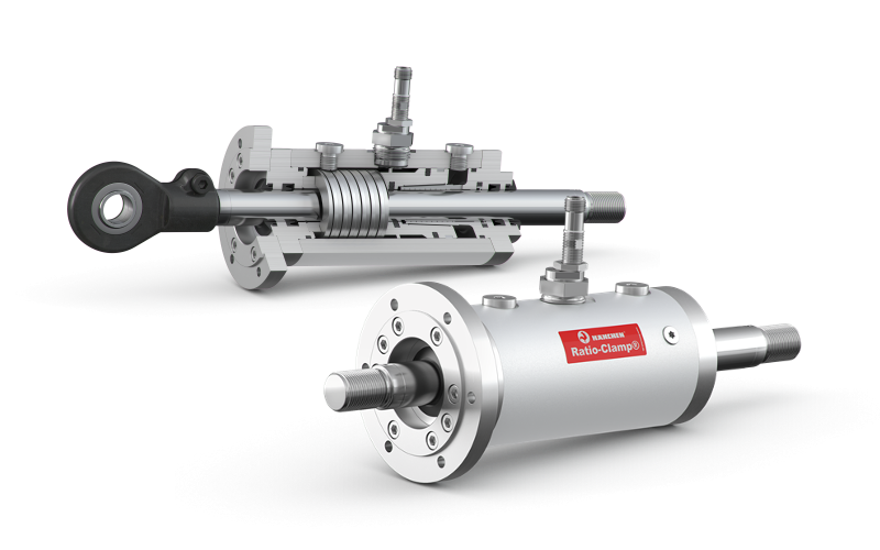
We offer rod-locks (Ratio Clamp®) as an optional feature for standard and custom hydraulic cylinders providing added security and functionality.
The Ratio Clamp® is a patented hydraulic clamping device that instantly locks piston rods or round rods, holding loads up to 2,000 kN. This device incorporates a spring force that clamps the rod securely in place without continuous energy, releasing only when hydraulic pressure is applied. Since these rod locks are mechanically locking and hydraulically unlocking, they also can be used as a safety device. This is an easy way to hold a cylinder in position indefinitely while not requiring any input from your HPU (saves money too!).
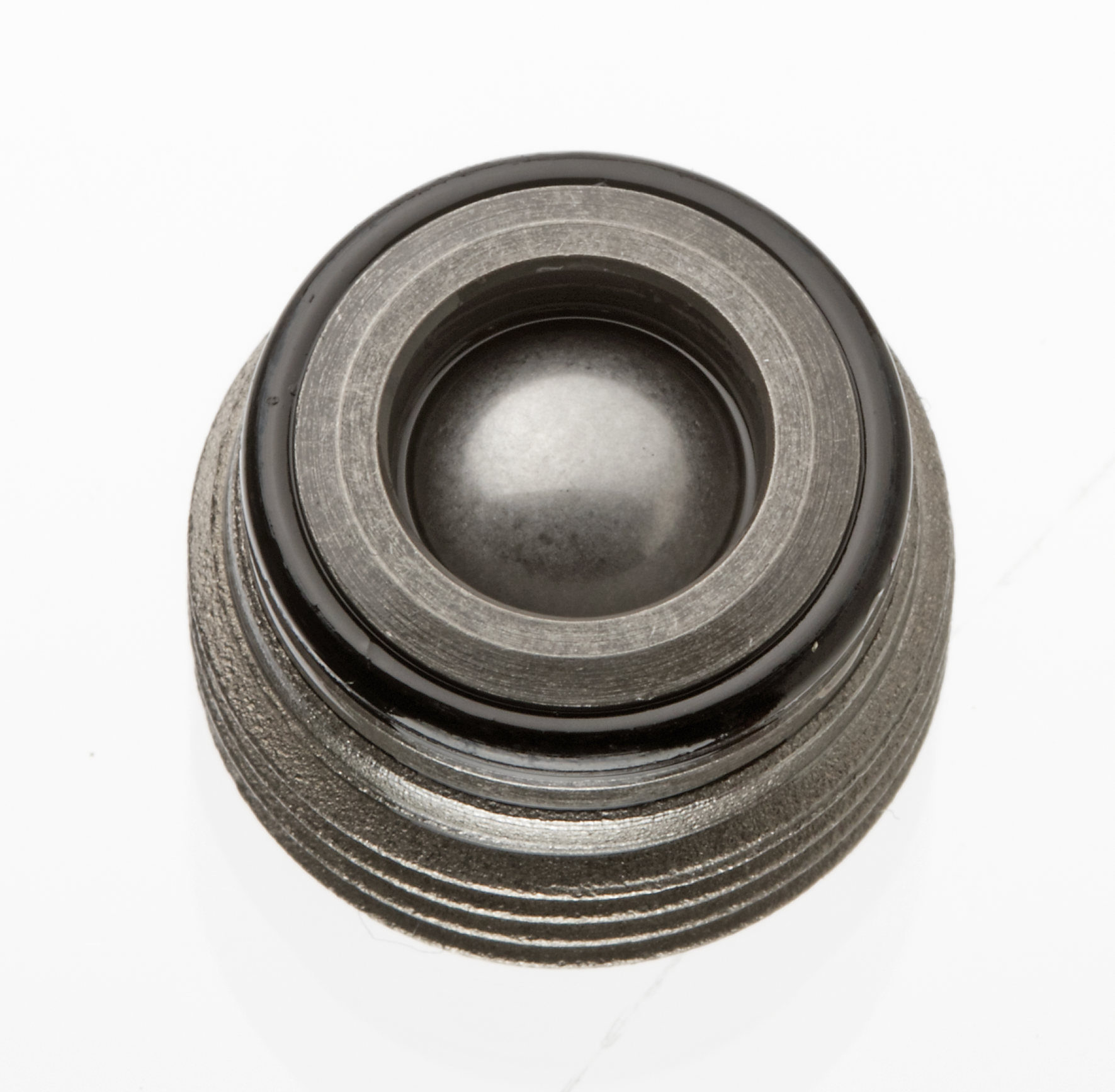
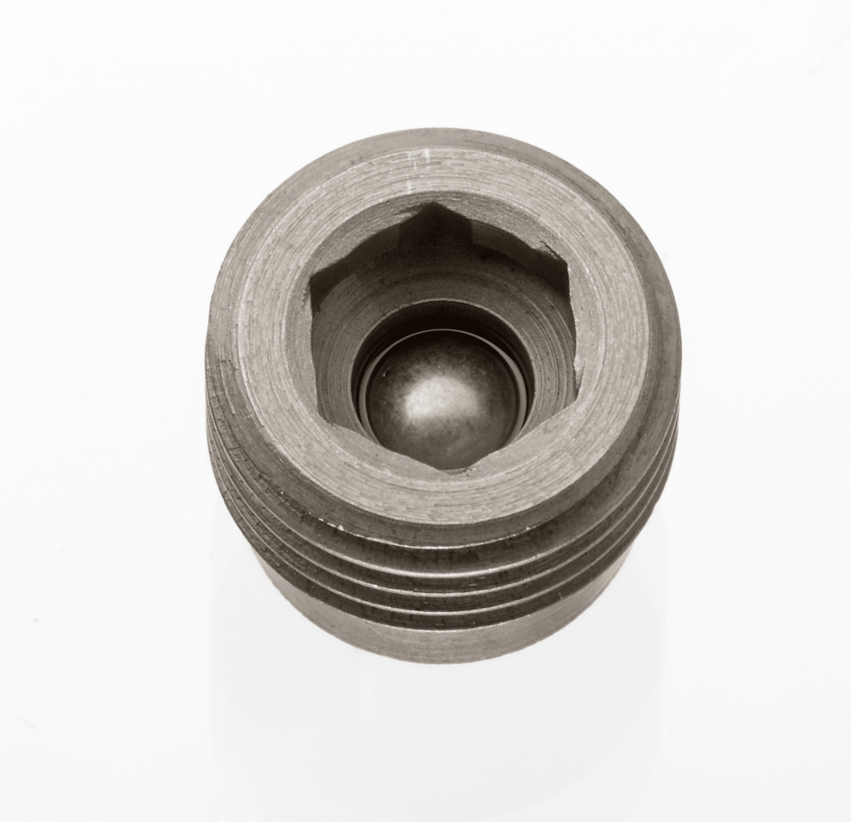
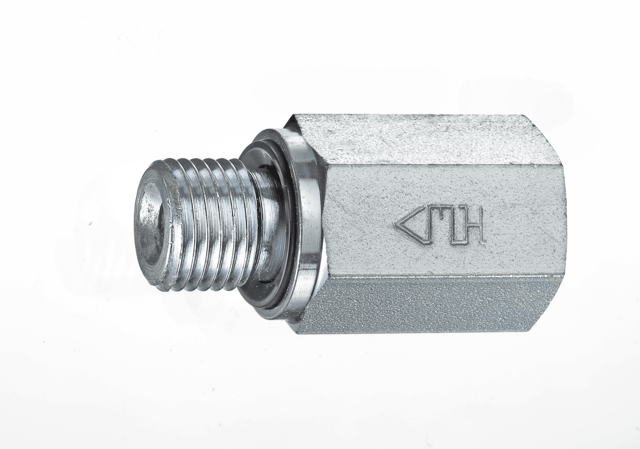
Check valves block an oil flow in one direction and allow it in the other direction. They are a type of shutoff valve. The check valve is inserted when an oil flow shall be allowed in one direction only. Meanwhile, the usage of check valves prevents backflow of the fluid.
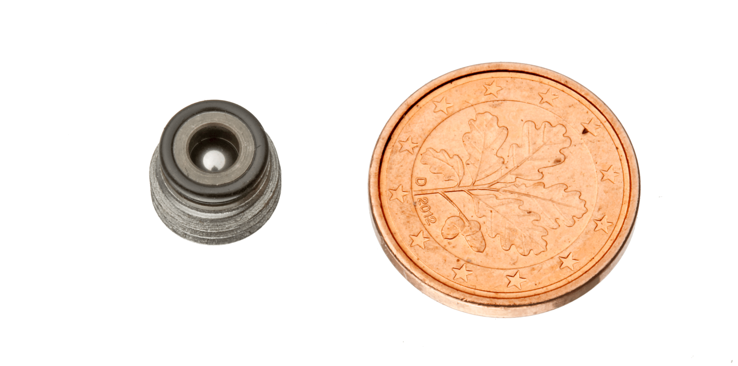
Advantages at a Glance:
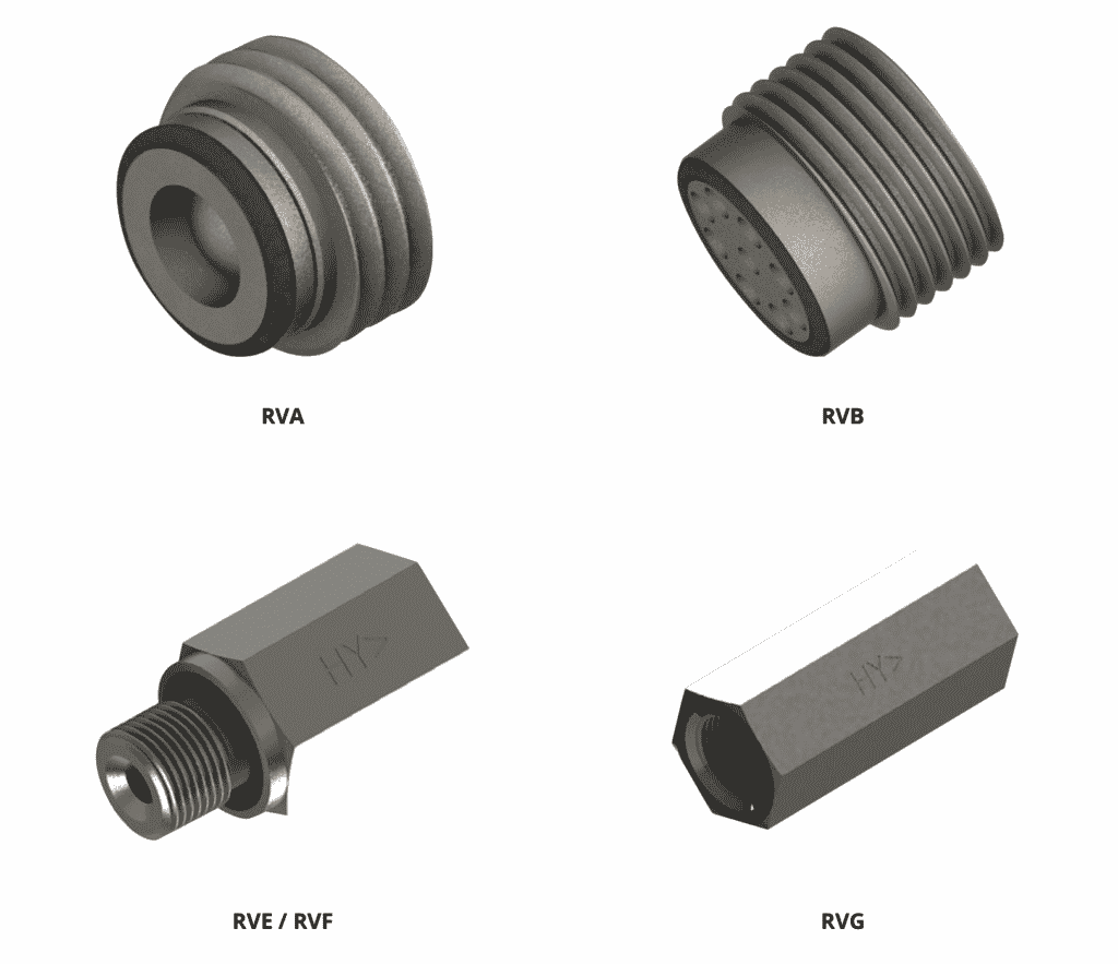
Spherical shell
Available as screw-in or caged version
Nominal size 1/16 – 1/8 – 1/4 – 3/8 – 1/2 – 3/4
Working pressure 10,000 psi
BSP or metric thread
The HYTORC-check valves are available with a screw-in or caged design. Even so, both designs can be obtained in two flow directions: with the screw-in direction closed or with free-flow. The spherical cap remains reliably tight in every position, in case of multiple switching cycles and under severe stress.
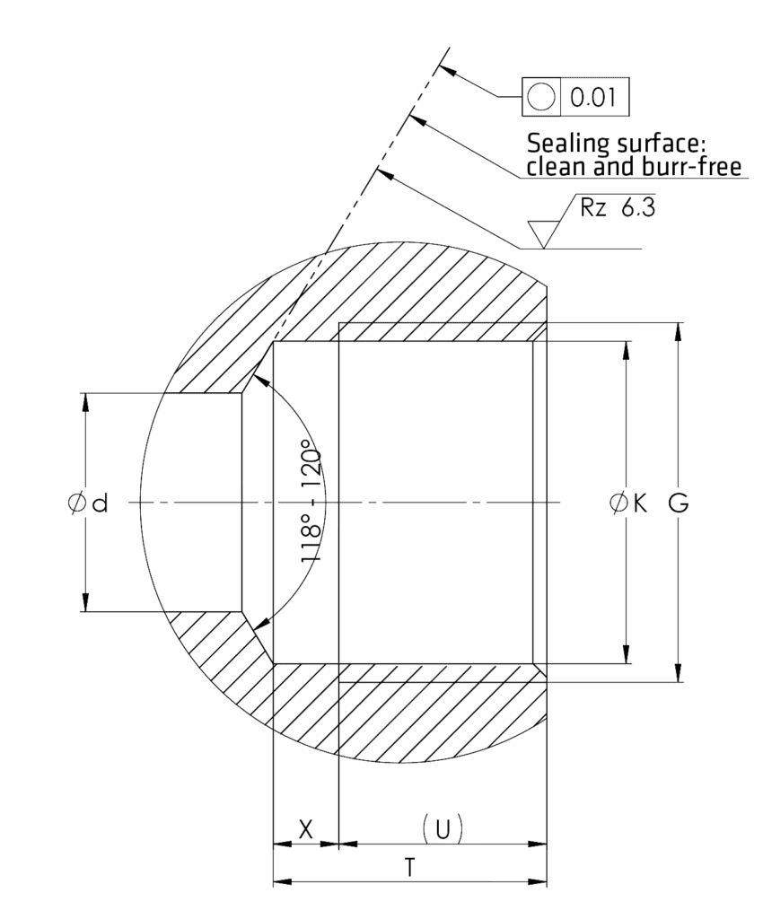
The HYTORC check valve easily screws into a regular hole (Dimensions screw-in drill). The screw-in check valves are sealed through an edge sealing which is turned to the cage. The edge sealing, together with the drill draft, forms a gap-free chamber for the O-Ring. The gap-free chamber and the O-Ring are repeatable sealing.
The valve is made of a high-strength hardened steel. Moreover, the ball seat is specially treated and the spherical shell is manufactured with a high tensile hardened and polished ball bearing ball. Thus, the design of the check valves is compact and economical which saves space and offers simple installation.
Use the widget tool below to find the right check valve type for your application.
Check Valve Type Selector Widget
Then refer to the drop down menus to find the technical information for your desired check valve model.
Technical Data
Permissible Operating Pressure
up to 10,000 psi (700 bar) (lock pressure)
Permissible Temperature
–40 to +176 °F (–40º +80°C)
Viscosity
5–500 cSt
Installation Position
any
Material
Body: normal and stainless Steel Gasket: NBR rubber
Screw-In Check Valve
Order No.
Type
G
L
a
n
z x d
o-ring
12 011 102
RVA 2-M
M 6
6
3.4
3.4
4 x 1.2
2.5 x 1
12 011 103
RVA 3-M
M 8×1
6
3.3
4.7
6 x 1.6
4 x 1
12 011 104
RVA 4 (RVA 4-M)
G 1/8 M 10×1
6.7
3.5
6
6 x 1.8
6 x 1
12 011 106
RVA 6 (RVA 6-M)
G 1/4 M 14×1.5
8.2
4.8
8.9
8 x 2.15
9 x 1
12 011 108
RVA 8 (RVA 8-M)
G 3/8 M 18×1.5
10.1
5.6
10.8
8 x 3.2
11 x 1.5
12 011 110
RVA 10 (RVA 10-M)
G 1/2 M 22×1.5
11.6
6.8
14 (14.5)
8 x 3.8
14 x 1.5
12 011 116
RVA 16 (RVA 16-M)
G 3/4 M 27×2
14.2
7.8
18.5
8 x 4.6
18.77 x 1.78
Screw-In Drill
Type
G
K
d [max]
T [min]
U
X [max]
RVA 2-M
M 6
5H11
2
6
4.2
1.8
RVA 3-M
M 8×1
7H11
3.5
5.9
4.1
1.8
RVA 4 (RVA 4-M)
G 1/8 M 10×1
8.8H11 (9H11)
5
6.5
4.3
2.2
RVA 6 (RVA 6-M)
G 1/4 M 14×1.5
11.8H11 (12.5H11)
8
8
5.8
2.2
RVA 8 (RVA 8-M)
G 3/8 M 18×1.5
15.25H11 (16.5H11)
10
9.3
6.7
2.6
RVA 10 (RVA 10-M)
G 1/2 M 22×1.5
19H11 (20.5H11)
12
10.5
8
2.5
RVA 16 (RVA 16-M)
G 3/4 M 27×2
24.5H11 (25H11)
16
13
8.7
4.3
RVA Opening Pressure + Starting Torque
NG
2
3
4
6
8
10
16
Opening Pressure
bar
0.36
0.26
0.17
0.19
0.22
0.18
0.17
Starting Torque
Nm
6
8
12
20
25
40
80
Screw-In Check Valve
Order No.
Type
G
L
a
AF
o-ring
12 011 202
RVB 2-M
M 6
6.3
3.3
3
2.5 x 1
12 011 203
RVB 3-M
M 8×1
6.6
3.6
4
4 x 1
12 011 204
RVB 4 (RVB 4-M)
G 1/8 M 10×1
7.7
4.6
5
6 x 1
12 011 206
RVB 6 (RVB 6-M)
G 1/4 M 14×1.5
10
6.6
7
9 x 1
12 011 208
RVB 8 (RVB 8-M)
G 3/8 M 18×1.5
11.4
7.5
8
11 x 1.5
12 011 210
RVB 10 (RVB 10-M)
G 1/2 M 22×1.5
13.1
8
10
14 x 1.5
12 011 216
RVB 16 (RVB 16-M)
G 3/4 M 27×2
16.9
10.7
12
18.77 x 1.78
Screw-In Drill
Type
G
K
d [max]
T [min]
U
X [max]
RVA 2-M
M 6
5H11
2
6.7
4.2
2.2
RVA 3-M
M 8×1
7H11
3.5
6.5
4.4
2.1
RVA 4 (RVA 4-M)
G 1/8 M 10×1
8.8H11 (9H11)
5
7.5
5.3
2.2
RVA 6 (RVA 6-M)
G 1/4 M 14×1.5
11.8H11 (12.5H11)
8
10
7.6
2.4
RVA 8 (RVA 8-M)
G 3/8 M 18×1.5
15.25H11 (16.5H11)
10
10.9
8.6
2.3
RVA 10 (RVA 10-M)
G 1/2 M 22×1.5
19H11 (20.5H11)
12
12
9.1
2.9
RVA 16 (RVA 16-M)
G 3/4 M 27×2
24.5H11 (25H11)
16
15.5
11.5
4
RVB Opening Pressure and Starting Torque
NG
2
3
4
6
8
10
16
Opening Pressure
bar
0.77
0.47
0.22
0.22
0.2
0.23
0.2
Starting Torque
Nm
6
8
12
20
25
40
80
RVE Screw-In Socket with Elastic Sealing
Order No.
Type
G
L
t
O
AF
12 011 306
RVE 6
G 1/4
40
12
2.5
19
12 011 308
RVE 8
G 3/8
42
12
2.5
22
12 011 310
RVE 10
G 1/2
51
14
3
27
RVF Screw-In Socket with Elastic Sealing
Order No.
Type
G
L
t
O
AF
12 011 406
RVF 6
G 1/4
40
12
2.5
19
12 011 408
RVF 8
G 3/8
42
12
2.5
22
12 011 410
RVF 10
G 1/2
51
14
3
27
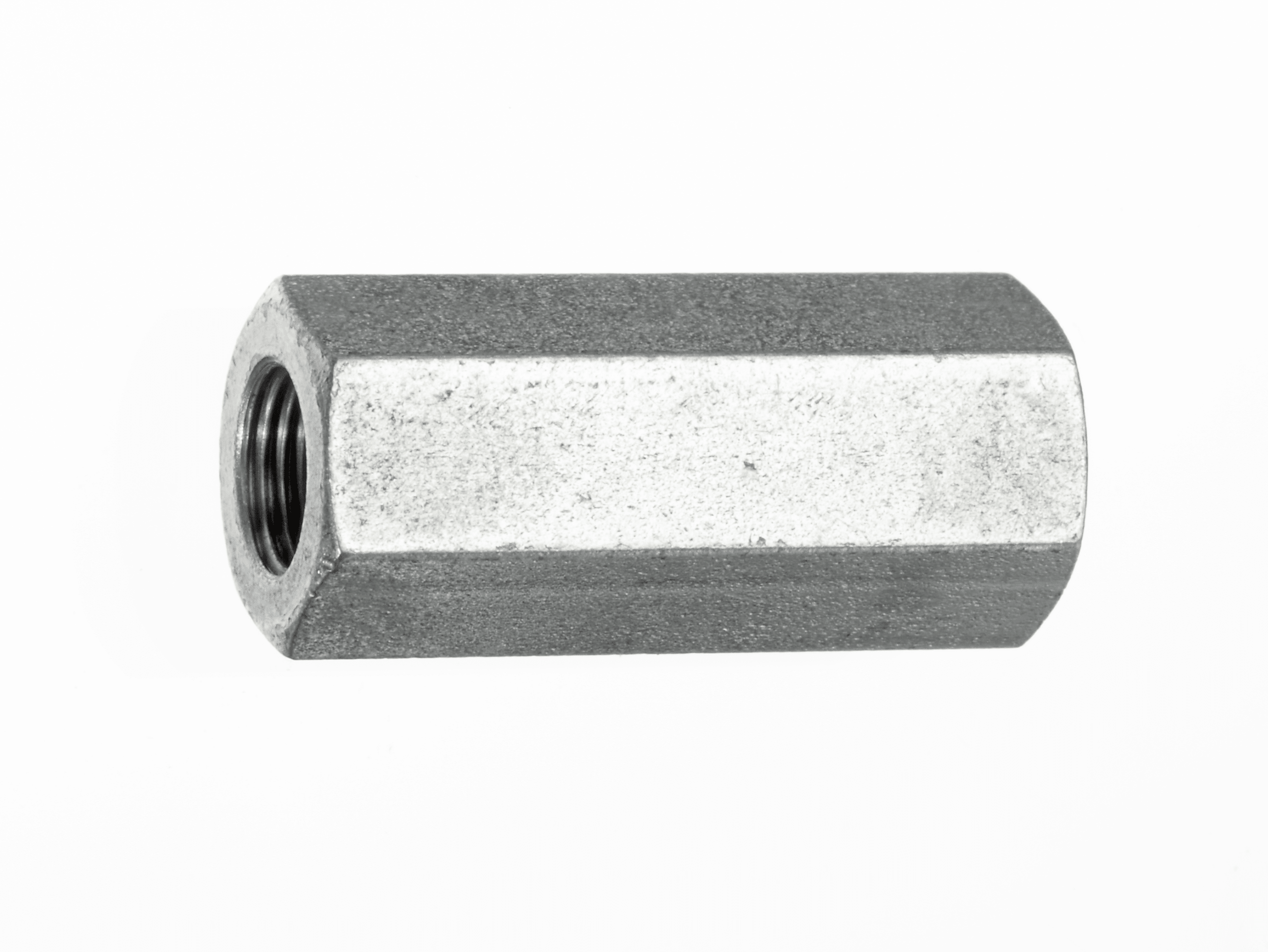
RVG Internal Thread on Both Sides
Order No.
Type
G
L
t
AF
12 011 506
RVG 6
G 1/4
45
12
19
12 011 508
RVG 8
G 3/8
48
12
22
12 011 510
RVG 10
G 1/2
58
14
27
RVA, RVE, RVG Flow Rate
Curve
Q Max l/min
1
=RVA2
3
2
=RVA3
6
3
=RVA4 – RVE4 – RVG4
10
4
=RVA6 – RVE6 – RVG6
25
5
=RVA8 – RVE8 – RVG8
45
6
=RVA10 – RVE10 – RVG10
70
7
=RVA16 – RVE16 – RVG16
100
RVB, RVF Flow Rate
Curve
Q Max l/min
8
=RVB2
2
9
=RVB3
4
10
=RVB4 – RVF4
8
11
=RVB6 – RVF6
18
12
=RVB8 – RVF8
30
13
=RVB10 – RVF10
60
14
=RVB16 – RVF16
90
Fitting Tools
Order No.
Desc.
for Type
b
zxd
c max
AF
9 05855 00
RMS 2
RVA 2
3.3
4×1
2
4
9 05855 00
RMS 3
RVA 3
4.7
3×1.5
1.9
8
9 05855 00
RMS 4
RVA 4
6
3×1.5
2.4
10
9 05855 00
RMS 6
RVA 6
8.9
4×2
2.7
12
9 05855 00
RMS 8
RVA 8
10.8
4×3
3.8
17
9 05855 00
RMS 10
RVA 10
14.5
4×3
4.5
19
9 05855 00
RMS 16
RVA 16
18.6
4×4
5.2
27
Hytorc is a supplier and power unit accessory and valve manufacturer for various applications including construction, mechanical, marine, and industrial.
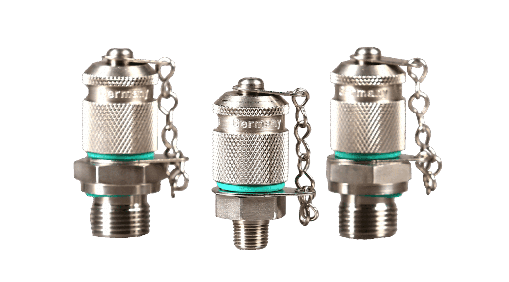
Test Points and Test Hose Assemblies Pressure is one of the most important diagnostic parameters in the hydraulic circuit. Obtaining… Read More »Test Points & Test Hose Specs
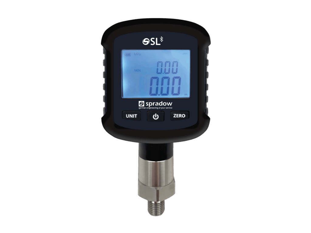
Smart Logger Pressure Gauge Smart Logger Bluetooth digital pressure gauges incorporate a high precision pressure sensor with an accurate LCD… Read More »Smart Logger Pressure Gauge
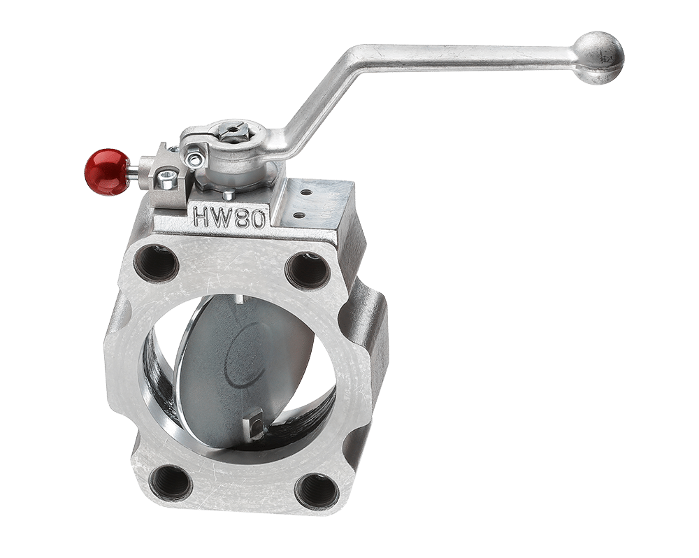
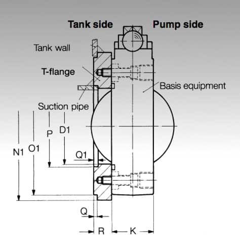
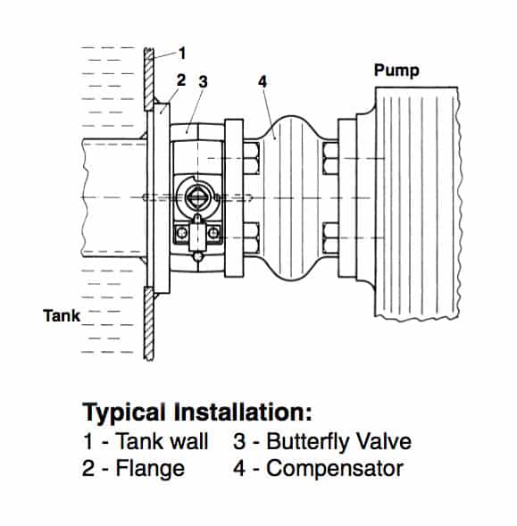
The Hytorc butterfly valve is a component designed to save time for the technician working on the hydraulic system by not having to drain the reservoir. The valve is designed for low pressure hydraulic lines up to 230 psi and can be installed into the pump suction line or mounted directly on to the hydraulic reservoir for example. The maximum pressure differential on either side of the valve should not exceed 58 psi when the valve is closed.
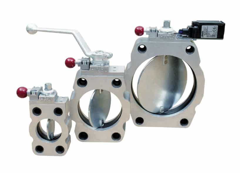
Hydraulic Butterfly Valves Features:
Thin profile and SAE flange for easy design into hydraulic circuits
Ideal for space limited mobile applications
28% more oil volume than ball valves
Simple maintenance; no reservoir draining
Equipped with a shifter for manual actuation
Easy installation for improved efficiency
Designed for low-pressure suction lines only
Automatic locking mechanism
Optional limit switch
Aluminum body for reduced weight
Low cost for large pipes
NBR seals ensure optimal sealing performance
Options: reservoir flange, limit switch, and threaded adapter brushing inserts
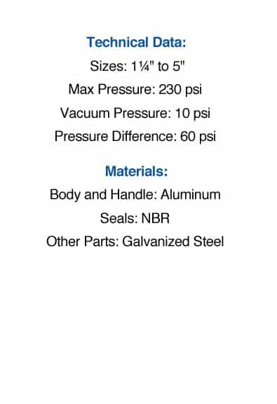
Technical Data and Specifications
Over pressure
232 psi (16.0 bar)
Under pressure
10 psi (0.7 bar)
Diff pressure when shut valve is closed
58 psi (4.0 bar)
Temperature range
-4ºF to 176ºF (-20ºC to 80ºC)
Material (Cage and Shifter)
Aluminum
Material (Sealings)
Nitrile Rubber (NBR) (Perbunan)
Material (Other Parts)
Galvanized Steel
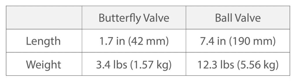
Comparing Size: Butterfly Valve versus Ball Valve on 4″ Pipe
For a 4″ pipe, butterfly valves are nearly 77% shorter and 71% lighter than a ball valve of the same diameter.
Ultra-compact profile to minimize space requirement:
In applications where fitting ball valves into the design poses a challenge, butterfly valves provide an effective solution. These valves are significantly shorter and lighter than their counterparts, facilitating easier handling and installation. The advantages of this design become increasingly evident as the nominal diameter rises. This is particularly beneficial in mobile hydraulics where space is a premium.
Convenient, simplified maintenance:
Thanks to internal clamping bolts, the valve is tightly secured to the reservoir even when even when disconnecting pipes or flexible connectors. This design enables maintenance without draining the reservoir.
Easy installation:
Shut off valves can be fitted between flanges due to the lateral recesses. Alternatively, heavy suction pipes can be held with additional screws.
No loss of oil volume:
The valve’s inner diameter is larger than the pipe, enabling full flow capacity without compromising on oil volume. This feature is crucial for maintaining efficient and precise control.
Automatic locking mechanism:
The self-engaging lock bar provides a secure and stable connection. The lock bar automatically engages in all switch positions; fully open, closed, or at an intermediate position, and ensures arresting of the valve’s position even without a shift lever.
Limit switch for preventative measures:
Prevent damage to your pump by making sure the valve is open prior to turning on the pump.
Ordering Code
AB 16 S [NG] – T H B E
The example for a shut off valve with a nominal width of 80mm, tank welded flange, shifter and limit switch is: AB 16 S 80 – THE
Hytorc is a supplier and power unit accessory and valve manufacturer for various applications including construction, mechanical, marine, and industrial.
Test Points and Test Hose Assemblies Pressure is one of the most important diagnostic parameters in the hydraulic circuit. Obtaining… Read More »Test Points & Test Hose Specs
Smart Logger Pressure Gauge Smart Logger Bluetooth digital pressure gauges incorporate a high precision pressure sensor with an accurate LCD… Read More »Smart Logger Pressure Gauge
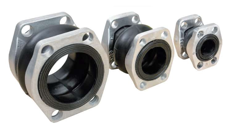
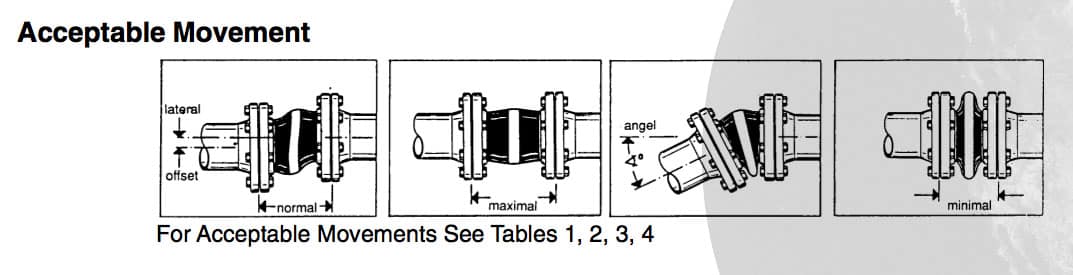
The HYTORC Rubber Compensator is a product that qualifies as one of the best kept secrets of power unit accessories. The compensators are flexible connectors with SAE or DIN flanges that correct pipe alignment problems. They also provide a benefit with damping of vibrations, noises and movements in axial and transverse direction.
The HYTORC Compensator is constructed of an inner liner of a reinforced high strength nitrile rubber (Perbunan). The outer and inside layers are smooth and have an aerodynamic design that eliminates cavitation. Both ends have a vulcanized sealing surface, eliminating the need of additional seals. The maximum operating pressure is 116 psi (6 bar) from -4 °F to +176 °F (-20ºC to 80ºC).
All types of mineral oil products, crude oil, lubricants, coolants, grease, cold water, warm water up to 140ºF (60ºC), water-oil-emulsion, fuels with up to 30% aromatics content
Ordering Code
K 16 S D – 80
The above example shows a compensator of a nominal width of 80mm with 1 SAE flange and 1 DIN flange.
HYTORC product designation
Form of execution, flange 1
S
Aluminum Alloy
ST
Galvanized Steel (SAE Flange)
D
Galvanized Steel (DIN Flange)
R
Malleable Cast Iron, Galvanized
Form of execution, flange 2
S
Aluminum Alloy
ST
Galvanized Steel (SAE Flange)
D
Galvanized Steel (DIN Flange)
R
Malleable Cast Iron, Galvanized
Nominal size
Hytorc is a supplier and power unit accessory and valve manufacturer for various applications including construction, mechanical, marine, and industrial.
Test Points and Test Hose Assemblies Pressure is one of the most important diagnostic parameters in the hydraulic circuit. Obtaining… Read More »Test Points & Test Hose Specs
Smart Logger Pressure Gauge Smart Logger Bluetooth digital pressure gauges incorporate a high precision pressure sensor with an accurate LCD… Read More »Smart Logger Pressure Gauge
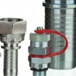
Thermoplastic hose fittings are offered by ZEC in galvanized steel and stainless steel. The fittings can be used at high pressure in the oil-hydraulics, lubrication and high temperature sectors, as well as for gasses, solvents and paints, and chemical products.
Product Features:
Reduced weight and size thanks to the use of raw materials of improved toughness and low specific weight
Excellent resistance to fatigue stress, alternating flexing, and vibrations
Due to the low surface roughness of approximately 0.6 microns, Zec’s thermoplastic hoses achieve minimal head loss and increased flow rates
Extremely long lifespan thanks to the exceptional anti-aging qualities of the techno polymers used
ZEC is a supplier and thermoplastic tubing and hoses manufacturer for various applications including construction, mechanical, technological, and industrial.
A wide variety of thermoplastic hose materials such as Rilsan PA11, Polyamide 12, Polyurethane, Hytrel, Polyethylene, and Ptfe are available to suit your low-pressure application
Hydraulic Hoses – Medium, High and Very High Pressure Thermoplastic Hoses
Medium, high and very high pressure flexible thermoplastic hoses and PTFE from ZEC can be used for applications in the pneumatics and oil-hydraulics fields and in lubrication, as well as for solvents and paints, gasses, chemical products and high temperature. They meet the main international SAE, ISO and EN regulations.
Product Features:
Reduced weight and size thanks to the use of raw materials of improved toughness and low specific weight
Excellent resistance to fatigue stress, alternating flexing, and vibrations
Due to the low surface roughness of approximately 0.6 microns, Zec’s thermoplastic hoses achieve minimal head loss and increased flow rates
Extremely long lifespan thanks to the exceptional anti-aging qualities of the techno polymers used
ZEC is a supplier and thermoplastic tubing and hoses manufacturer for various applications including construction, mechanical, technological, and industrial.
A wide variety of thermoplastic hose materials such as Rilsan PA11, Polyamide 12, Polyurethane, Hytrel, Polyethylene, and Ptfe are available to suit your low-pressure application
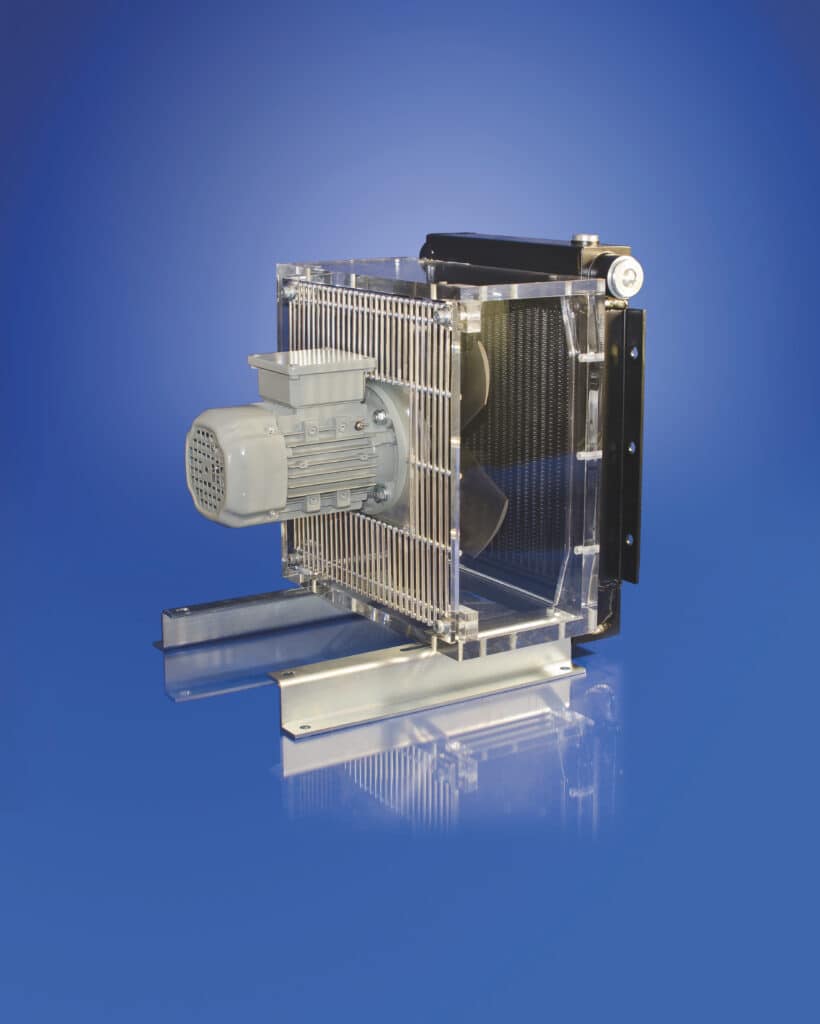
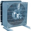
The Universal Hydraulik TFS/A series is a compact partial-flow cooling unit. It was developed to improve the availability and reliability of hydraulic systems. Due to its combination of a motor pump unit and an oil-air cooler in one device, the TFS/A is an autonomous unit, which can be operated independently of the main system. In this manner continuous cooling is ensured.
Product Features
Compact design
Nearly noiseless operation
Ease of maintenance, since the number of working parts has been consequently reduced
Equipped with multi range motors as standard equipment
Any arbitrary mounting position is possible
Options:
Test pressure 580 psi (40 bar)
Filter mat
Ceiling-, wall-, or floor-mounting position
Thermo-bypass valve
Thermal Switch
Stainless Steel
Thermostat
Product Advantages:
Extension of the service life of the hydraulic components
Enhancement of the application reliability
Improvement of the positioning accuracy
Uncomplicated retrofitting on existing systems is possible
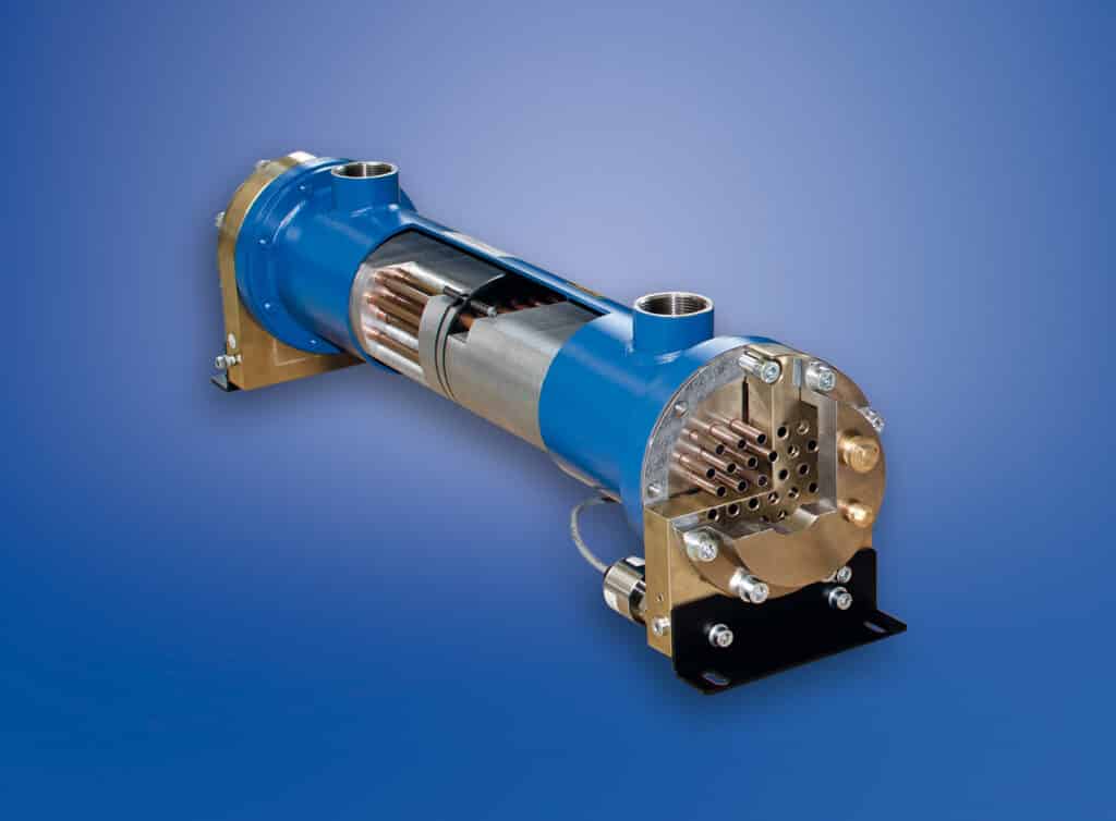
Universal Hydraulik is a supplier and heat exchanger manufacturer for various applications including construction, mechanical, marine, and industrial.
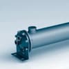
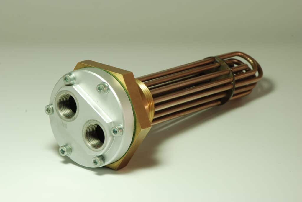
Bare tube heat exchangers are an ideal choice for cooling high viscosity fluids and particle containing fluids that may clog a cooler with internal cooling fins.
Fail-safe coolers prevent the mixture of fluids should one of the cooling tubes fail. This is achieved by double wall tubes and safety switches that indicate a tube failure.
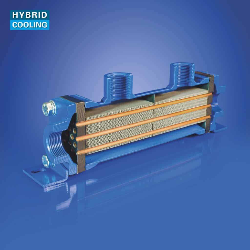
Hybrid heat exchangers combine the advantages of shell & tube and plate heat exchangers. The larger surface area permits a physically smaller heat exchanger with better cooling capacity.