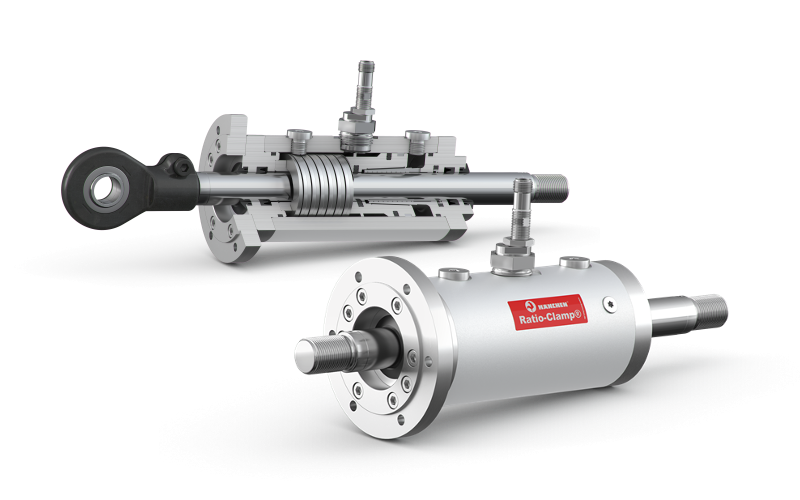
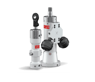
Hydraulic Test Cylinders
For over 100 years, Hänchen has supported the test and simulation industry with actuators built for precision and durability. Our servo cylinders cover one of the widest ranges on the market. Choose from lightweight models for simple tests (Series 120/300) to hydrostatic models for demanding, high-frequency applications (Series 320). With patented sealing technologies found nowhere else in the market and highly-honed surface finishes, Hänchen cylinders last for decades in service.
One of the largest testing ranges in the market, offering lightweight models for static applications or high frequency cylinders for dynamic testing.
Need Support? We Can Help.
What Makes Us Different?
Largest Testing Range on the Market
o Offering lightweight servo actuators for static applications and ultra-rigid cylinders for dynamic testing.
12 Sealing Combos for Low Friction and Stick-Slip
Customize your cylinder for static or dynamic loads with patented sealing technology to minimize friction, stiction, and side loads.
Fast Lead Times with Competitive Pricing
Competitive pricing and fast manufacturing (as quick as 14-18 weeks) compared to popular brands, like MTS.
Test Cylinders 101
What are Test Cylinders?
Test cylinders are used extensively in the testing sector and can be used for checking the functional safety of systems, component parts or products, for structural testing of airplanes, refrigeration compressors, automobile exhaust systems, or for simulating loads and movements, such as operational profiles and flight profiles.
Product Benefits
Stick-Slip in Hydraulic Cylinders
Our Hydrostatic Design
Hydraulic Test Cylinder Sealing Options
Tell us about your application, and we will help you find the perfect seal. Any solution is possible for your application. We make patented and standard seals for low friction, side loading, high pressures, rotation, fast/slow movement, stroke amplitude, and medium compatibility.
In the following chart, the first row of images and titles denote sealing systems, while the first column on the left denotes guiding systems.
|
Basic Design 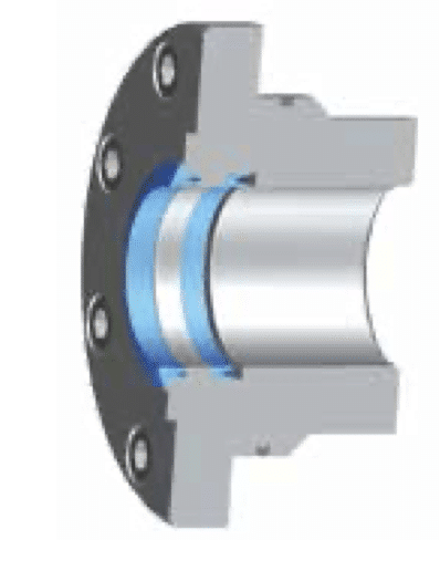
|
Servocop® 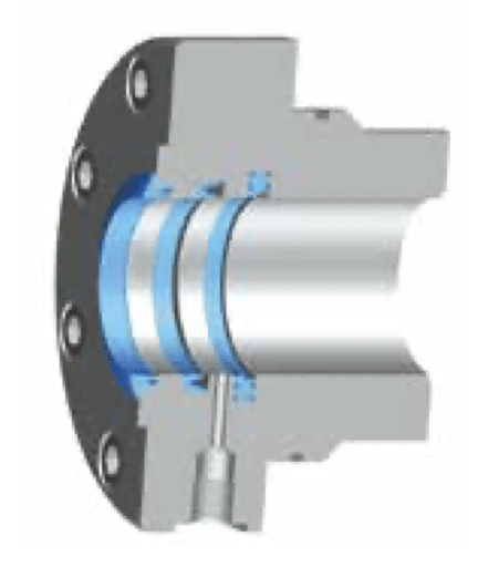
|
Servoseal® 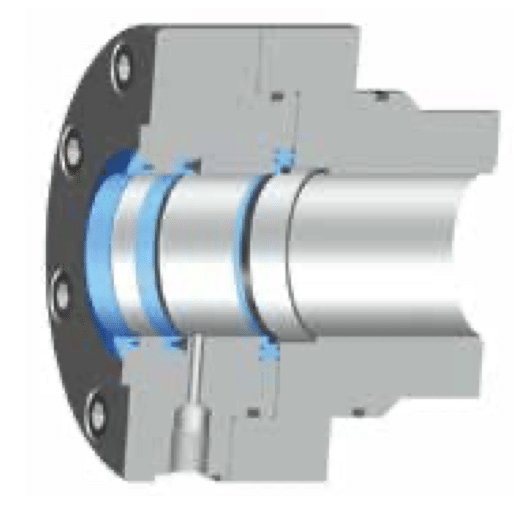
|
Servofloat® 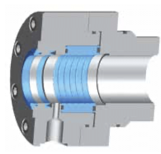
|
Functional oil seal 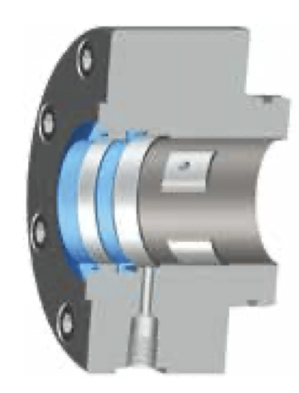
| |
|
Servoslide® 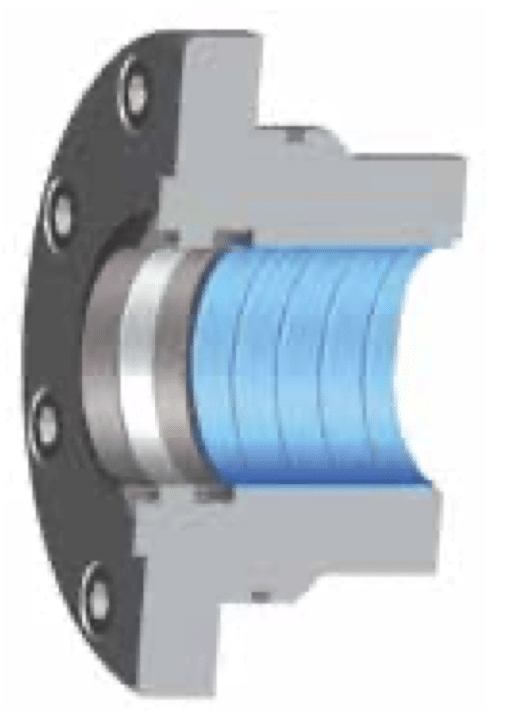
|
– Simple movements |
– Controlled movements |
– Sensitive movements |
– Sensitive movements | |
|
Metallic guide 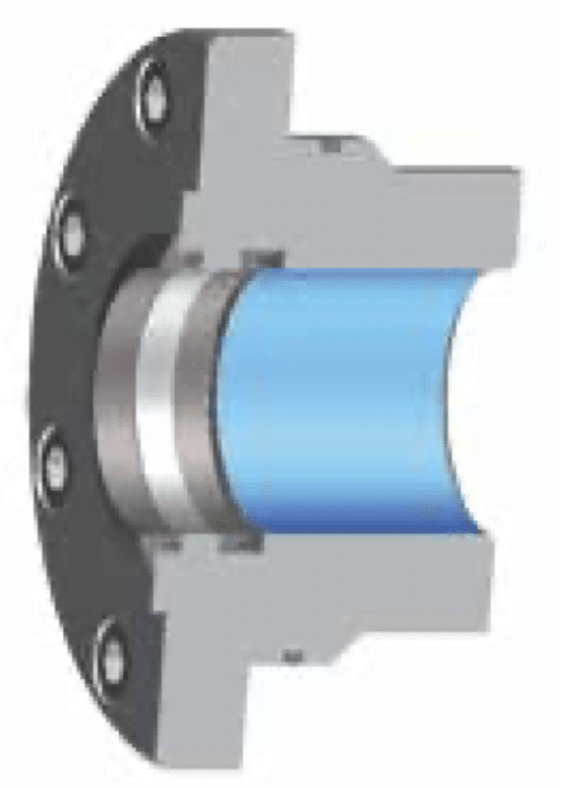
|
– Simple movements |
– Simple movements |
– Simple movements |
– Simple movements | |
|
PTFE Wear rings 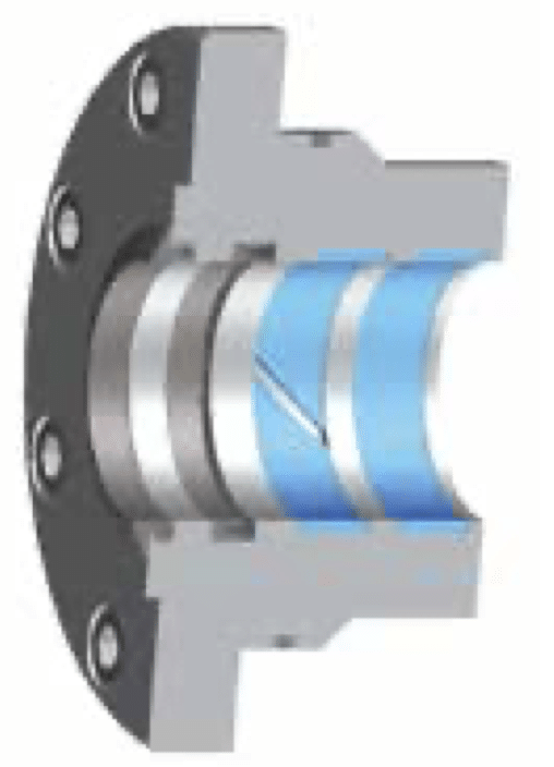
|
– Controlled movements |
– Sensitive movements |
– Sensitive movements | ||
|
Servobear® 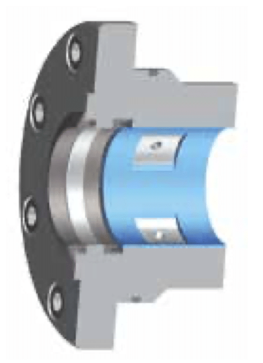
|
– Sensitive movements |
Application Examples and Solutions
Hydraulic Test Cylinders are used in a wide variety of applications including automotive testing such as lifecycle tests, aerospace system tests such as load and environmental condition simulation, and fluid power operating condition simulation.
Automotive
Servo hydraulic lifecycle tests are the current industry standard for automobile components that are used far beyond safety-related structural elements. Users can depend on hydraulic test actuators for high positioning accuracy and reliability in applications for test systems and real time control. A test cylinder with a dynamic lift of up to 35 mm (1.3 in.), speed of 1.3 m/s (51.2 in/s), and acceleration of up to 50 m/s (1968.5 in/s) could be used for a test load requiring up to 28 kN (6,294 lbf) and a frequency up to 20 Hz.
Aerospace
System tests that simulate loads and environmental conditions in different flight phases are particularly demanding. To test the landing flaps and slats, servo hydraulic cylinders could be used here to replicate the airflow that involves rapidly changing forces with irregular parameters. For example, a servo cylinder with a bore between 40 to 160 mm (1.5 to 6.2 in.) could be used for a test stand with a holding force between 140 – 300 kN (31.4 to 67.4 lbf) and a stroke requirement of 300 to 1,670 mm (11.8 to 65.7 in.).
Fluid Power
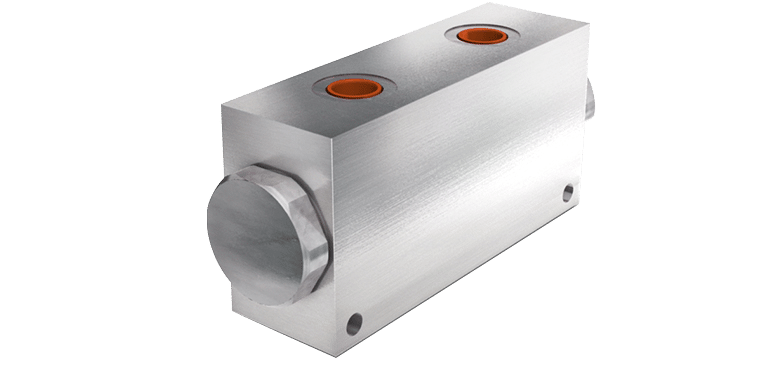
To determine the characteristic values of a seal, seal test benches are suitable for simulating a wide range of operating conditions. Double rod cylinders could be used here for fatigue tests focused on examining the frictional force of the seals, tightness on rods and shafts.
Frequently Asked Questions
The maximum speed is limited by the seal solution, which is the type of seal configuration and/or the material.
In the following charts, the numbers on the right denote the maximum velocity in meters per second (v max in m/s).
Sealing system in cover
|
0.5 |
1 |
2 |
3 |
4 | |
|
Basic sealing system |
+ |
– |
– |
– |
– |
|
Servocop® |
+ |
+ |
+ |
+ |
– |
|
Servoseal® |
+ |
+ |
+ |
+ |
– |
|
Servofloat® |
+ |
+ |
+ |
+ |
+ |
|
Floating oil seal |
+ |
+ |
+ |
+ |
+ |
Guiding system in cover
|
0.5 |
1 |
2 |
3 |
4 | |
|
Servoslide® |
+ |
+ |
+ |
– |
– |
|
Metallic guide |
+ |
+ |
– |
– |
– |
|
PTFE wear rings |
+ |
+ |
+ |
+ |
+ |
|
Servobear® |
+ |
+ |
+ |
+ |
+ |
Sealing system on the piston
|
0.5 |
1 |
2 |
3 |
4 | |
|
Rectangular compact seal |
+ |
+ |
+ |
+ |
+ |
|
Rectangular compact seal with elastomer |
+ |
– |
– |
– |
– |
|
Throttle gap |
+ |
+ |
+ |
+ |
+ |
|
Servoseal® |
+ |
+ |
+ |
+ |
+ |
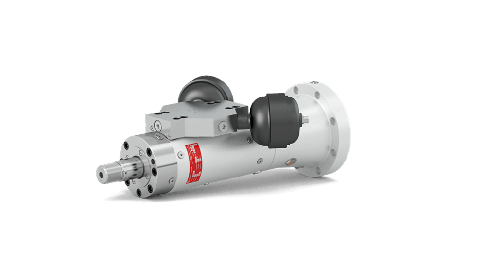
Series 320
The Series 320 cylinders are used in highly dynamic testing and motion control applications where high cycling accuracy is required, oftentimes with low amplitudes. It supports variable displacement profiles with stable performance under load.
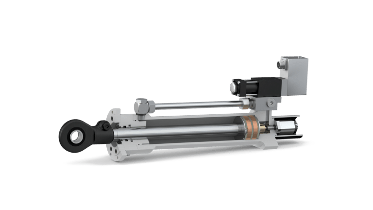
Series 120 and 300
The Series 120 and 300 cylinders are designed as compact alternatives to classic test actuators for simple testing tasks. When equipped with a mounting plate and position transducer, they deliver precise performance for static and dynamic test applications.
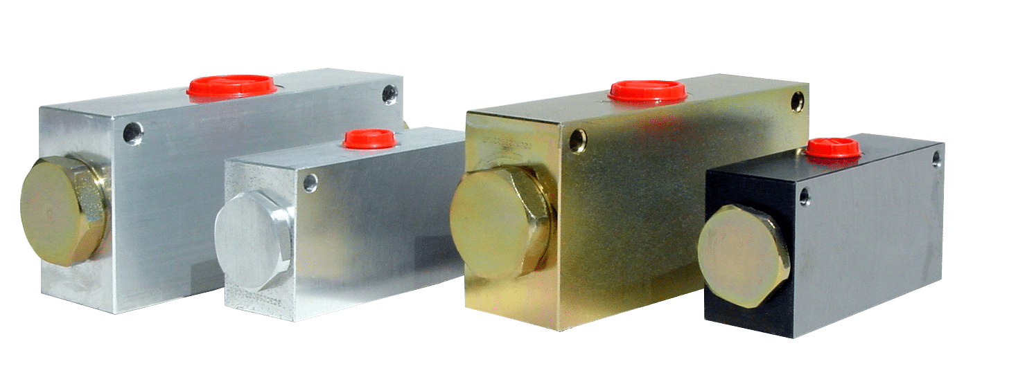
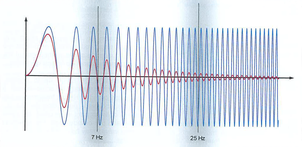
Choosing a single or double-rod cylinder depends on the force ratios, dynamics, and lateral vibrations.
Single-rod, Series 120, 300 (up to 7 Hz)
Single-rod cylinders are suitable for moderate dynamics with frequencies up to 7 Hz. Higher frequencies can also be achieved, depending on the dynamics of the control valve used, the travel speed, and the cylinder size. Asymmetrical control valves may have to be used for this purpose.
Double-rod, Series 120, 300 (up to 25 Hz)
Above a certain dynamic, it is advisable to work with equally large effective areas on the cylinder. For example, it is recommended to use double-rod cylinders for up to 25 Hz, as most control valves have symmetrical surfaces.
Besides the hydraulic limits, even the mechanical properties play an important role. At exceptionally high frequencies, very heavy and stiff cylinders are preferred to prevent the cylinder from swinging up due to transverse acceleration. For example, this can be achieved by using heavy, conical protection tubes.
Double-rod, Series 320 (above 25 Hz)
For applications exceeding 25 Hz, the Series 320 is recommended.
For short strokes or low-amplitude movements (for example, around ±1 mm) over an extended period, contact seals can cause friction and significant wear because the surfaces move too little to maintain lubrication.
In such cases, non-contact sealing or guiding systems are recommended such as Hänchen’s Servobear® (commonly referred to as hydrostatic), Servoseal®, Servofloat®, or Servobear®). This design avoids surface scoring and provide smoother motion.
Sealing system in cover
|
“simple” long-stroke |
short-stroke oscillation | |
|
Basic sealing system |
+ |
– – |
|
Servocop® |
+ |
– |
|
Servoseal® |
+ |
+ |
|
Servofloat® |
+ |
+ |
|
Floating oil seal |
+ |
+ |
Guiding system in the cover
|
“simple” long-stroke |
short-stroke oscillation | |
|
Servoslide® |
+ |
– |
|
Metallic guide |
+ |
– – |
|
PTFE wear rings |
+ |
+ |
|
Servobear® |
+ |
+ |
Sealing system on the piston
|
“simple” long-stroke |
short-stroke oscillation | |
|
Rectangular compact seal |
+ |
– |
|
Rectangular compact seal with elastomer |
+ |
– – |
|
Throttle gap |
+ |
+ |
|
Servoseal® |
+ |
+ |