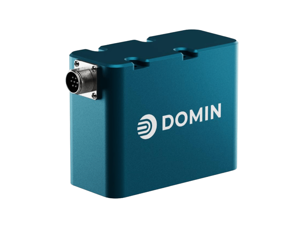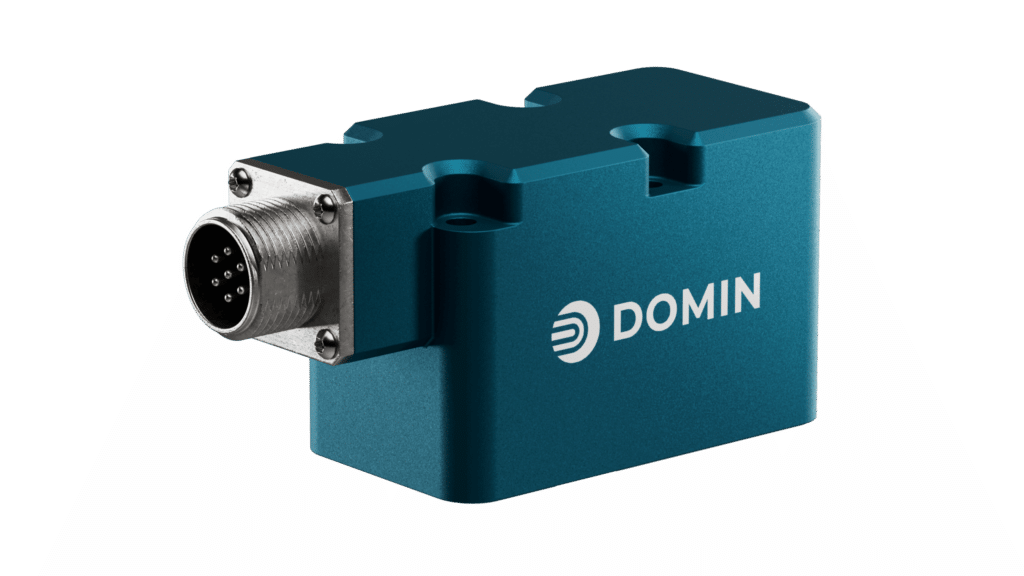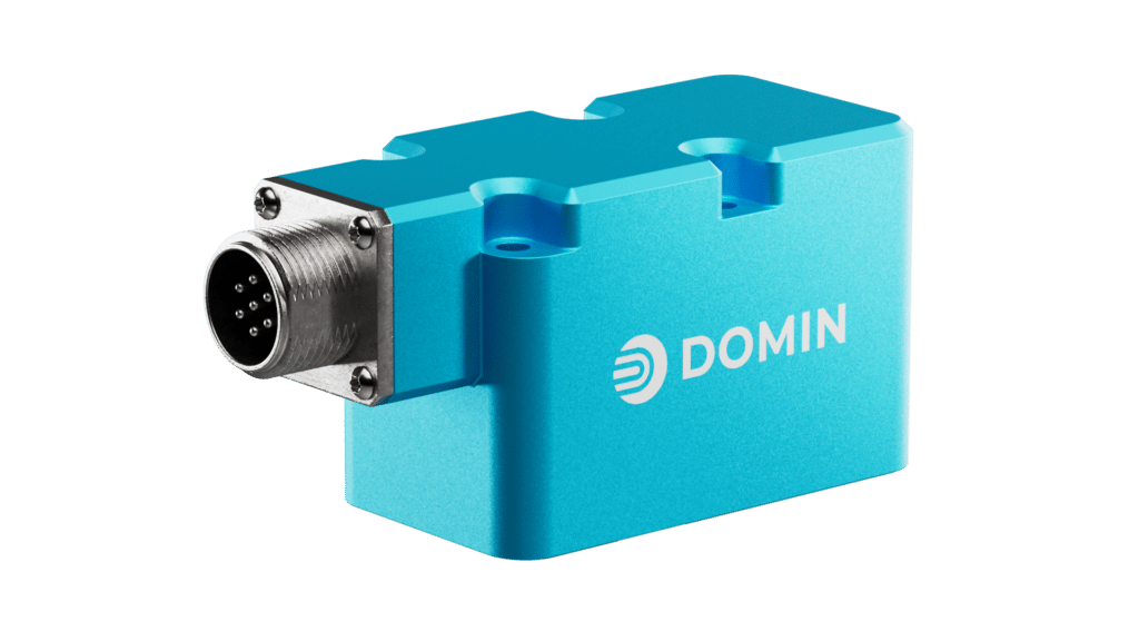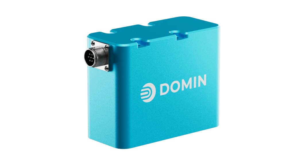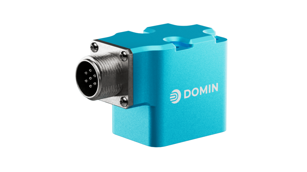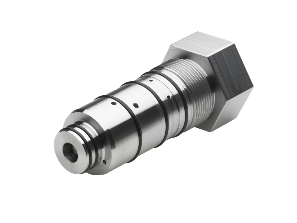
Hydraulic Servo Valves – S6 Pro
The Domin S6 Pro direct drive servo valve (DDV) has been designed to achieve the best characteristics from two competing valve technologies: fluid amplified EHSVs and DDVs. The S6 Pro has the size, mass, and dynamic capabilities of the most compact EHSV, and the low quiescent leakage and reliability of the best DDV.
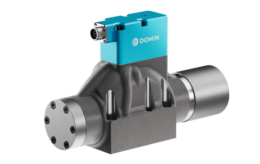
For applications requiring the results of the S6 Pro X, the S6 Pro model can be upgraded with a mounting plate adapter to achieve the same functionality.
Discover Ultimate Power Density
Experience optimal performance without compromise. Whether in test simulation or industrial manufacturing, the S6 Pro ensures seamless operations and maximum productivity, thanks to its superior design and exceptional power density.
With the Domin S6 Pro, you get the best of both worlds: the size, mass, dynamic capabilities, and industry-leading power density of the most advanced two-stage valves, paired with low quiescent leakage and unwavering reliability. Experience effortless efficiency, precision and power with the Domin S6 Pro series.
Available on NG06 port pattern as standard.
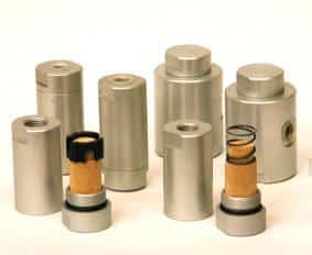
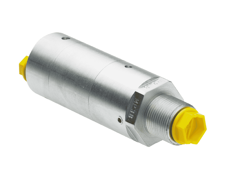
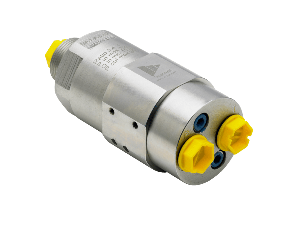
Popular Upgrade Models:
Key Stats:
Key Features:
Standard Modification Options:
Technical Data:
| Design | Direct Drive Servo Valve | |
| Actuation | Rotary-Linear | |
| Size | NG06 | |
| Mounting Interface | ISO 4401-03-02 | |
| Ambient Temperature | ºC (ºF) | -20 to +60 (-4 to +140) |
| Mass | kg (lb) | 0.62 (1.36) |
| Vibration Resistance, All Axes | g | 30 |
| Shock Resistance, All Axes | g | 50 |
| Max. Operating Pressure (P, A, B) | Bar (psi) | 350 (5,000) |
| Max. Operating Pressure (T) | Bar (psi) | 250 (3,600) |
| Fluid | Hydraulic Oil DIN 51524-535 | |
| Fluid Temperature | ºC (ºF) | -20 to +80 (-5 to +175) |
| Viscosity | cSt | 5 to 500 |
| Rated Flow | l/min (US gal / min) | 10 to 63 (2.6 to 16.6) |
| Flow Maximum | l/min (US gal / min) | 140 (36.9) |
| Leakage at 100 bar | l/min (US gal / min) | <1.1 (0.3) |
| Filtration | ISO 4406 (1999) 18/16/13 |
| Response Time at 100% Step Input | ms | <3.5 |
| Frequency Response (-3dB gain, ±25% signal) | Hz | >250 |
| Frequency Response (-90deg phase, ±25% signal) | Hz | >120 |
| Hysteresis | % | <0.2 |
| Threshold | % | <0.1 |
| Null Shift | % | <1 |
View performance graphs for the S6 Pro Domin Servo Valve below including Step Response, Flow vs Command, Frequency Response, and Pressure Gain:
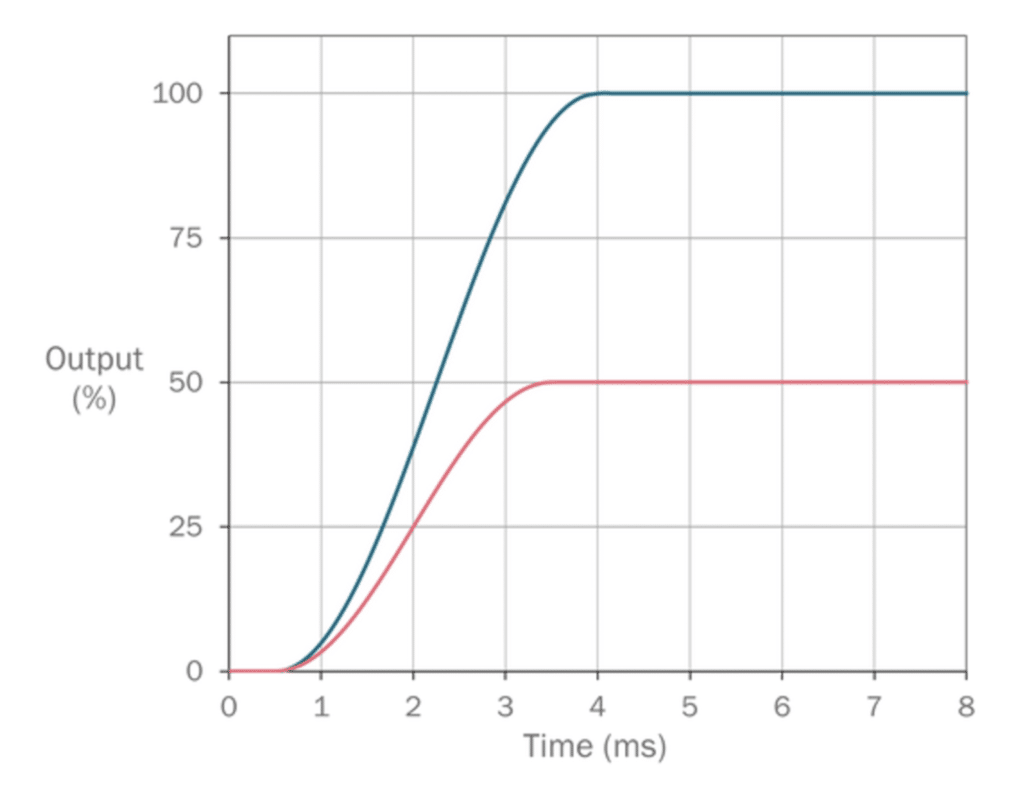
Step Response 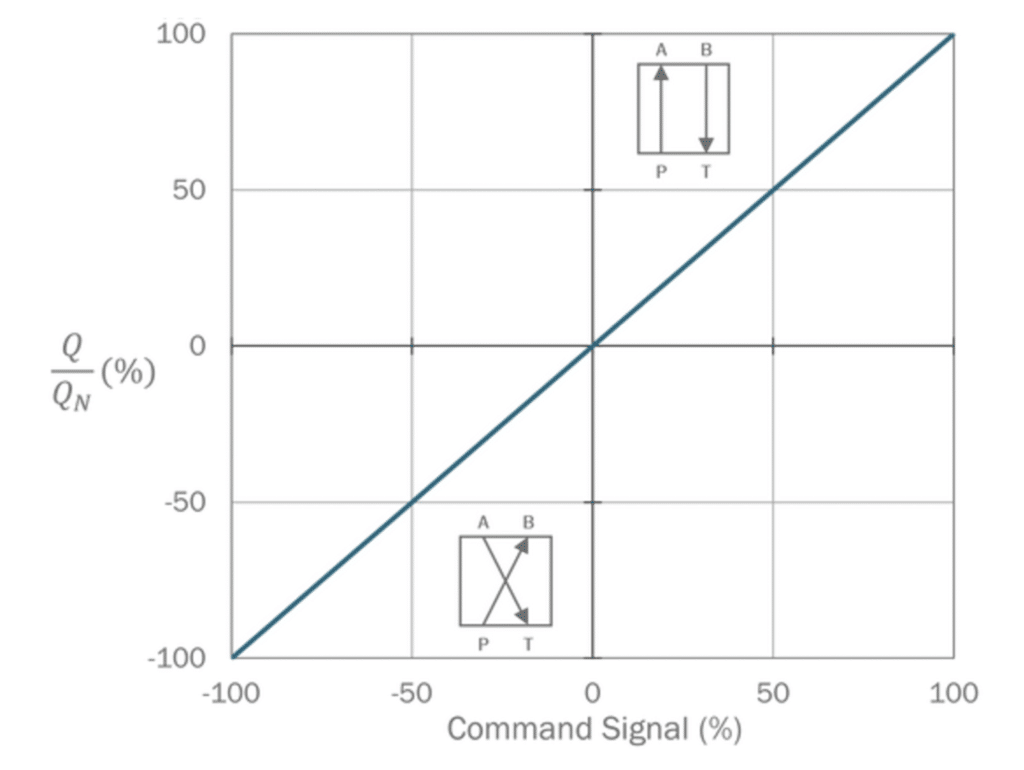
Flow vs Command 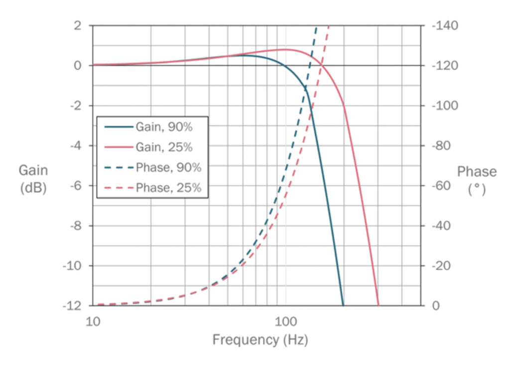
Frequency Response 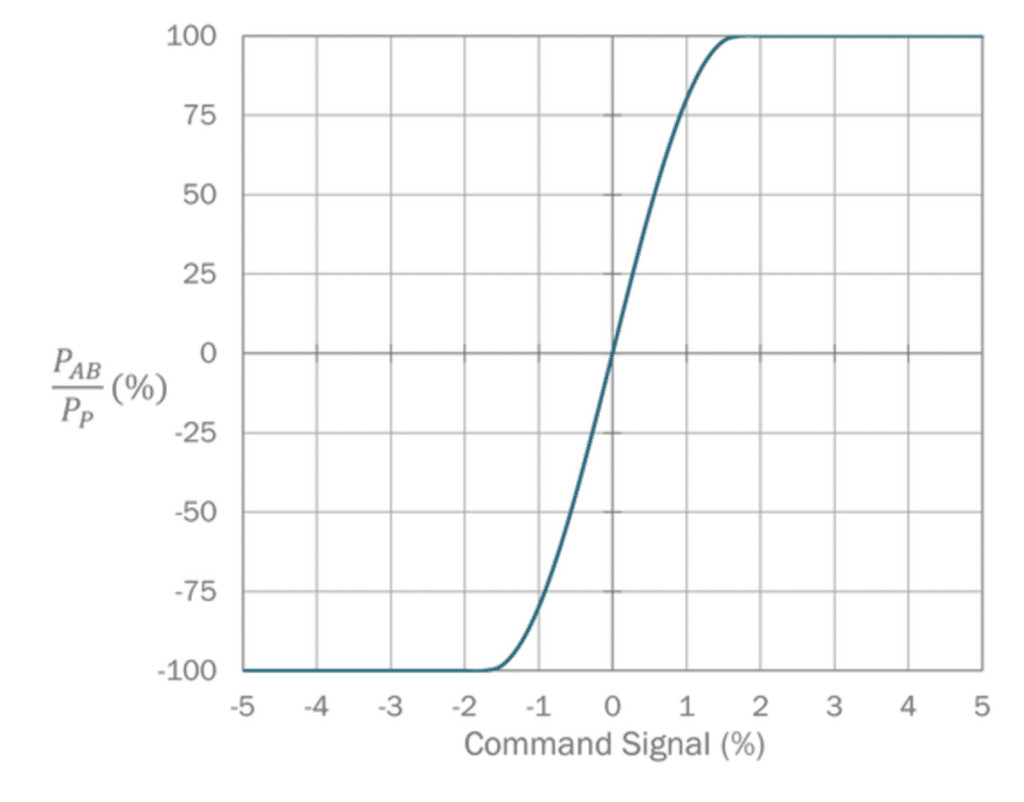
Pressure Gain


Ratings of the valve electronics vary based on selected command input.
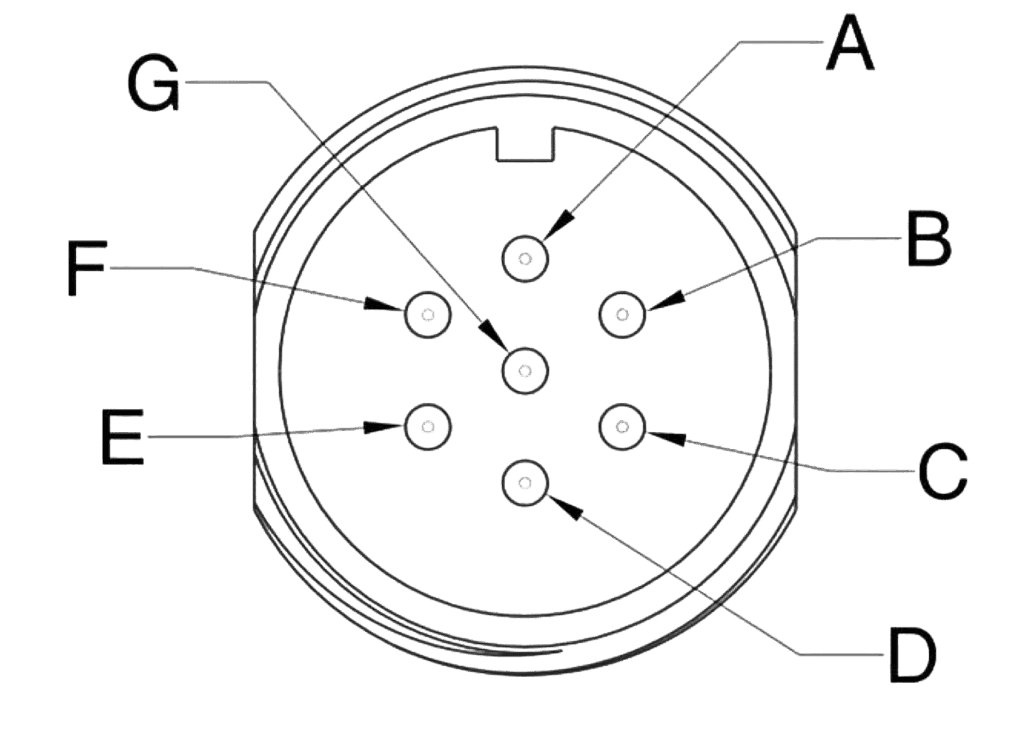
Type: Case Mounted
Termination: Connector according to EN 175201-804/MIL 5015 equivalent, shell size 14
Number of Contacts: 7
|
Pin |
Function |
Desc. |
|
A |
Supply + |
+24 V |
|
B |
Supply 0 V |
0 V |
|
C |
Output – |
Output 0 V Reference |
|
D |
Input + |
Differential Input, + |
|
E |
Input – |
Differential Input, – |
|
F |
Output + |
Output Signal |
|
G |
Earth |
– |
* When the enable function is selected, the function of pin C is the enable input. This replaces the standard pin function.
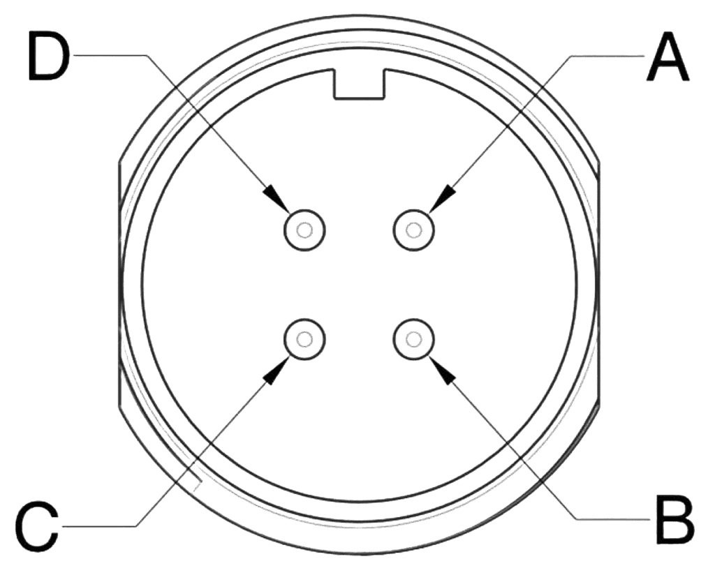
Type: Case Mounted
Termination: Connector according to EN 175201-804/MIL 5015 equivalent, shell size 14
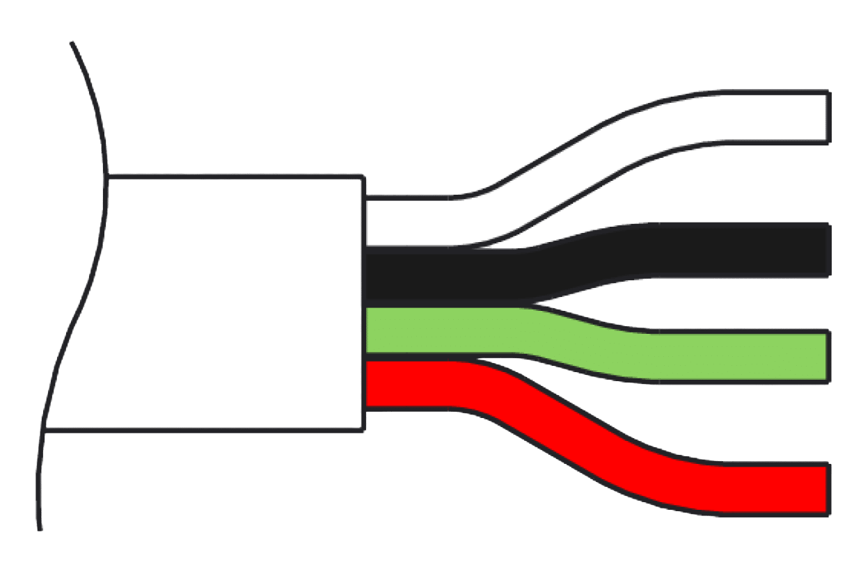
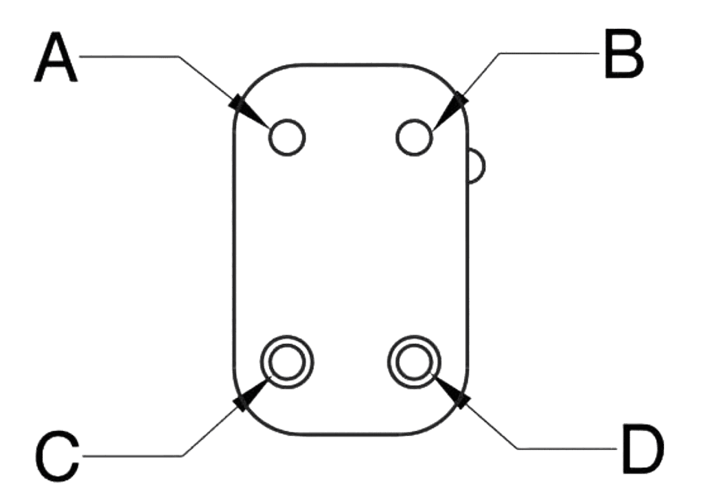
Number of Contacts: 4
|
Pin |
Function |
Desc. |
|
A |
Supply + |
+24 V |
|
B |
Input + |
Differential Input, + |
|
C |
Input – |
Differential Input, – |
|
D |
Supply 0 V |
0 V |
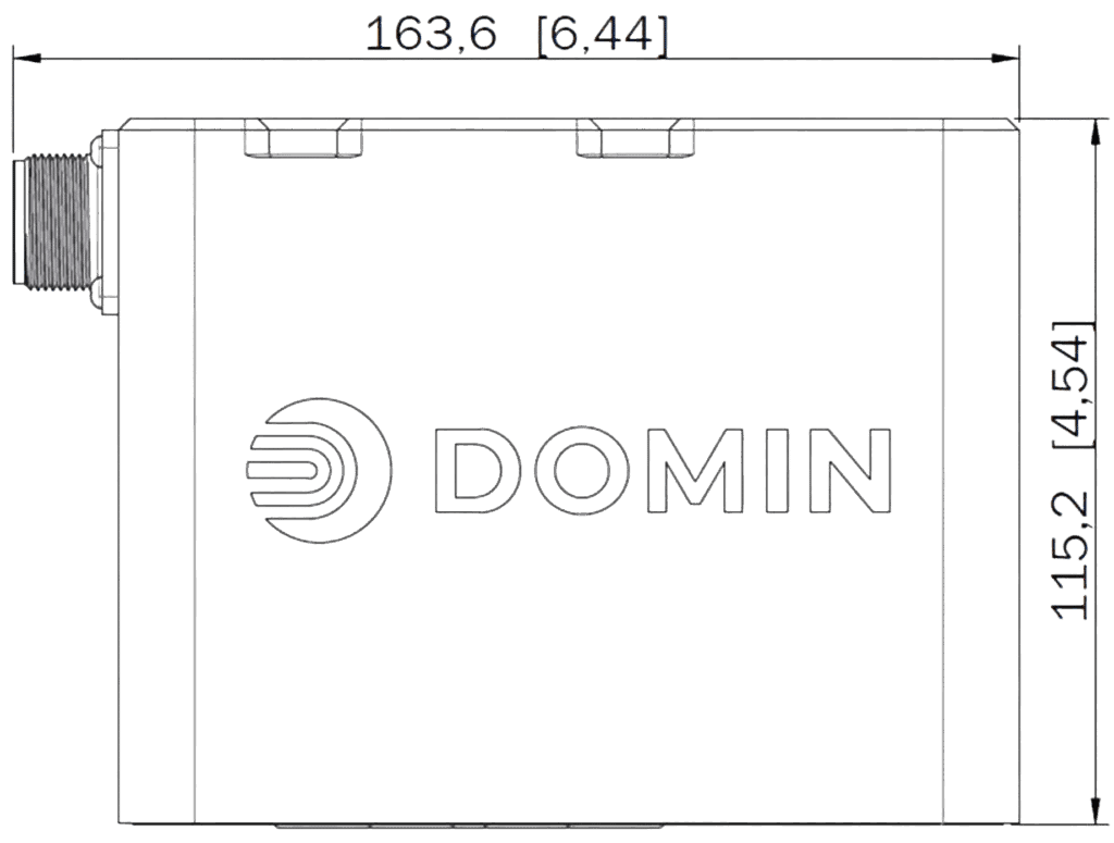
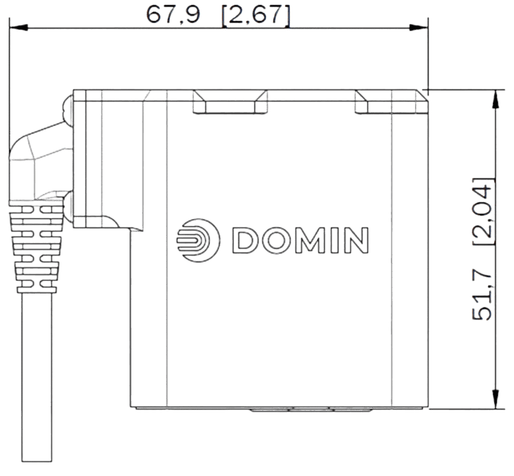
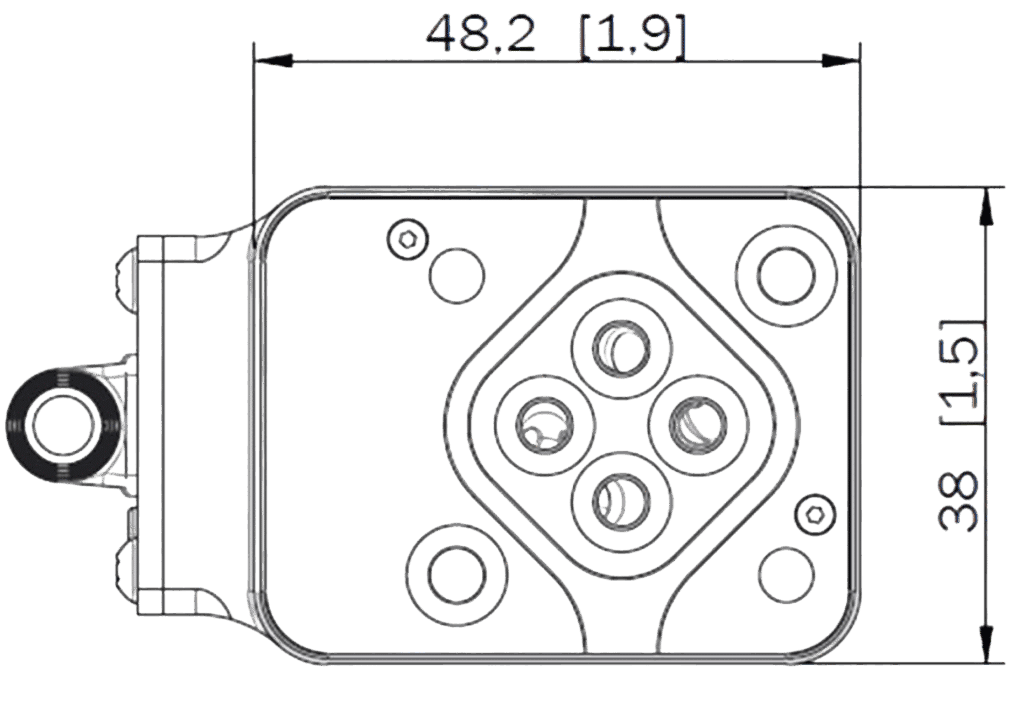
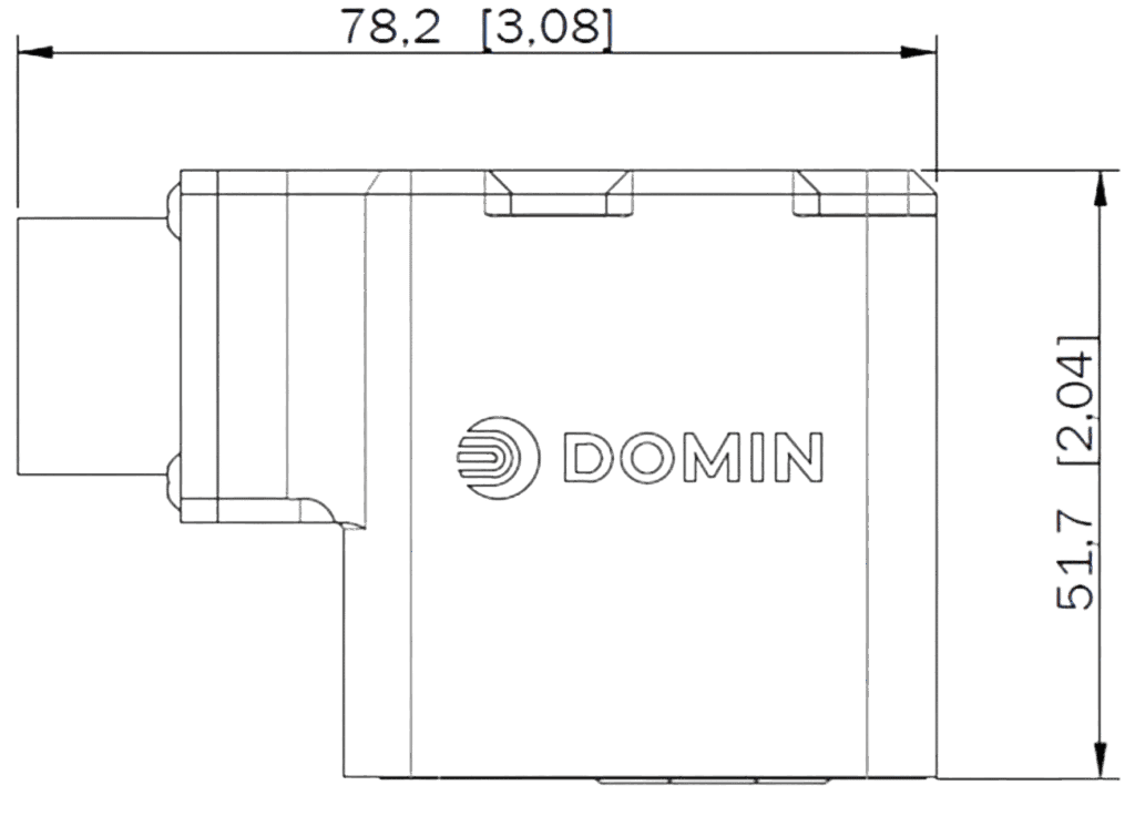
Unit Dimensions – Connector Code G and B4
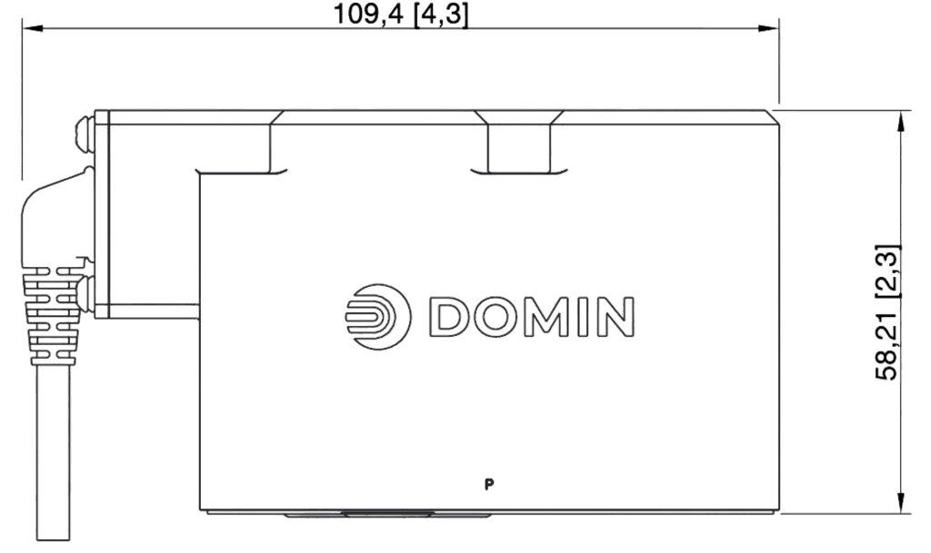
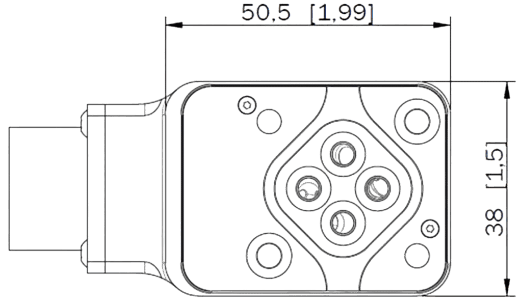
Unit Dimensions – Connector Code E and E4
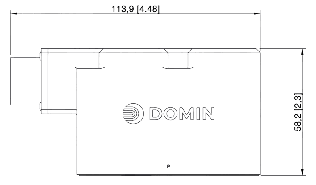
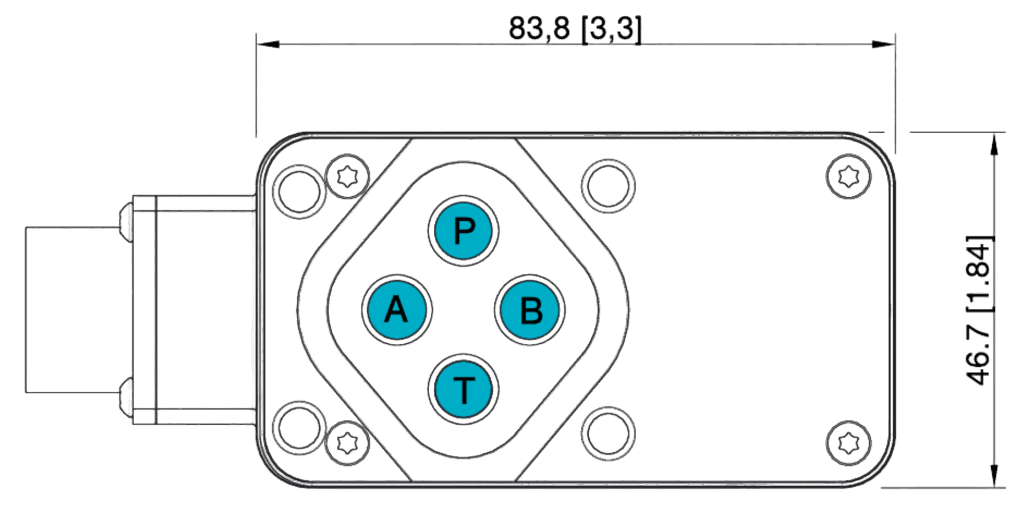
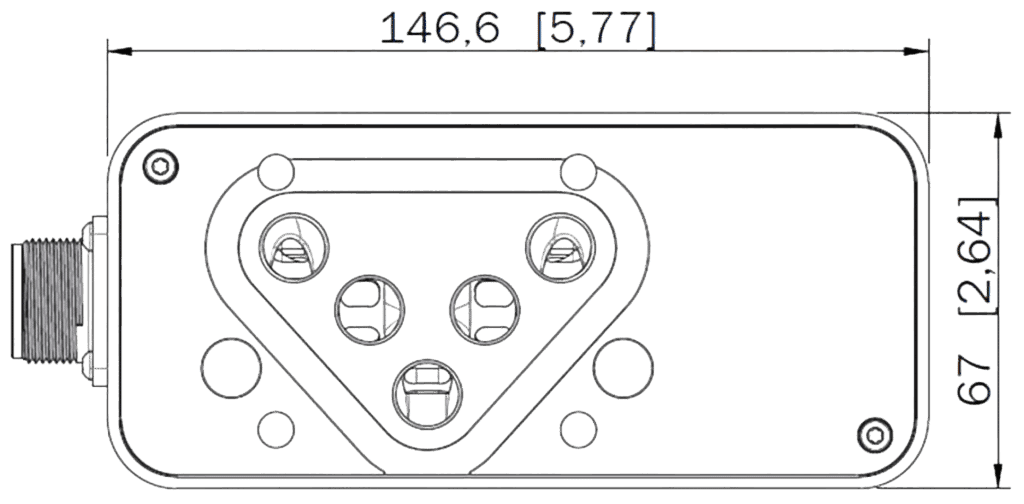
Nominal dimensions are displayed in mm. Bracketed dimensions are in inches. Not to scale. Note X and Y directions.
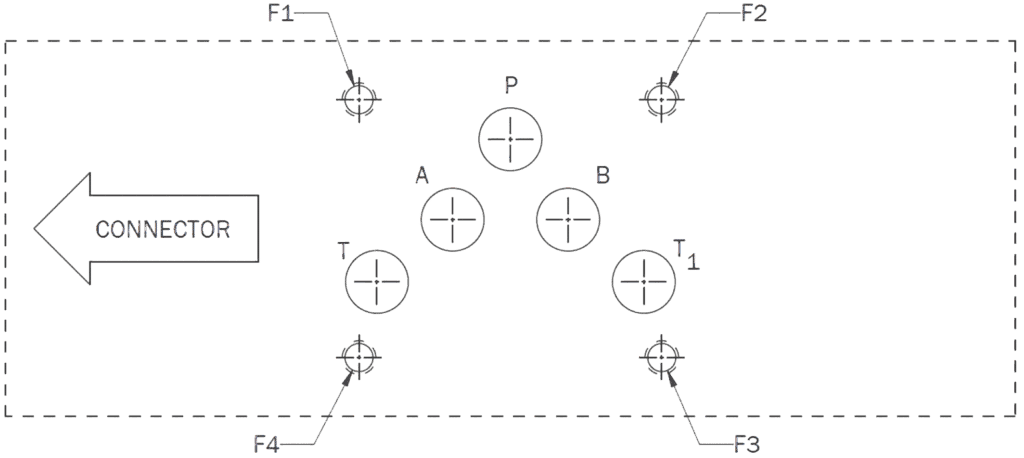
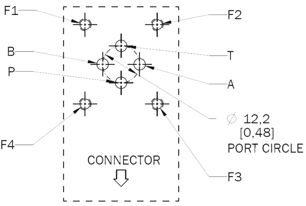
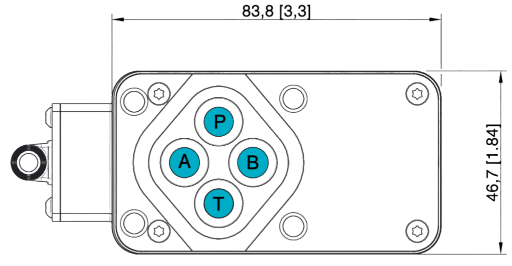
Mounting Surface Pattern Dimensions
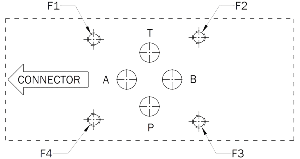
|
|
Dia Ø |
X Position |
Y Position |
|
P |
7.5 |
21.5 |
25.9 |
|
A |
7.5 |
12.7 |
15.5 |
|
B |
7.5 |
30.2 |
15.5 |
|
T |
7.5 |
21.5 |
5.1 |
|
F1 |
M5 |
0 |
0 |
|
F2 |
M5 |
40.5 |
-0.75 |
|
F3 |
M5 |
40.5 |
31.75 |
|
F4 |
M5 |
0 |
31 |
Bolts (F1, F2, F3, F4)
Type: M5 x 55 DIN EN ISO 4762-10.9
Required Torque: 7.5 Nm (5.5 ft-lbf)
O-Rings (P, A, B, T)
Type: 9.25 x Ø 1.78 (ISO 3601-1-008)
Material: NBR, EPDM or Viton, 70 Shore A
Hardness: 70 Shore A
Not to scale.
Standards Reference
EMC Regulations: EN 61000-6-2 / EN550011:1998+A1
Performance Tests: ISO 10770-1
Pressure Rating: ISO 10771
Hydraulics Interface: ISO 4401-03-02-0-05
Ordering Code
S6 Pro 1 2 3 4 5 6 7 8 9
Variants on Request
Domin is proud of their ability to offer tailored solutions that meet customers’ specific needs. If you require a non-standard configuration, or a bespoke modification, we are confident we can provide you with the best solution. Talk to us here and one of our team will respond as soon as possible.
Domin is a supplier and servo valve manufacturer for various applications including die casting, injection molding, wood/timber machines, vibration equipment, metal processing, and simulation.