HYDRAULIC PRESSURE INTENSIFIERS – MP-L SERIES


LOW/MEDIUM PRESSURE
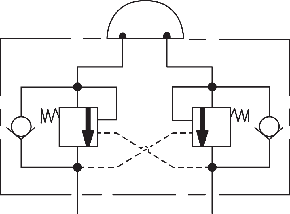
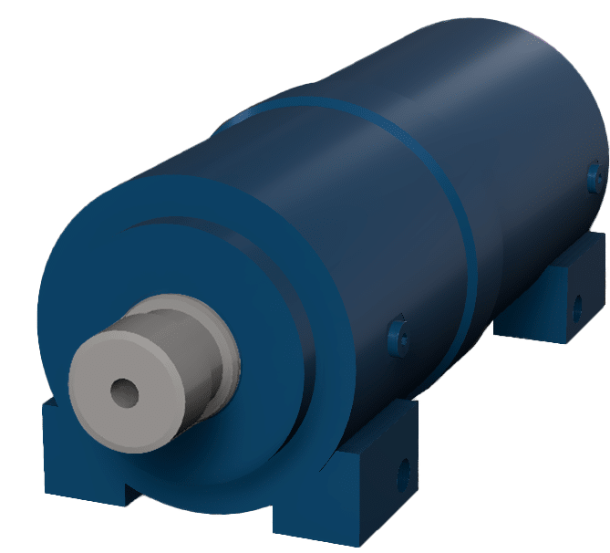
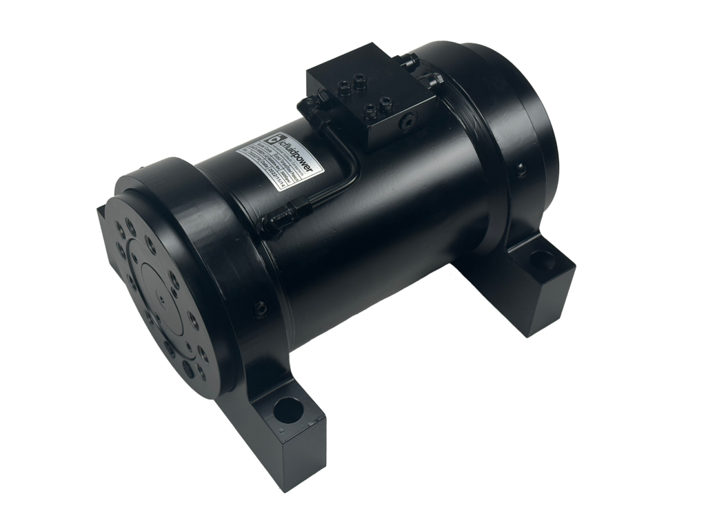
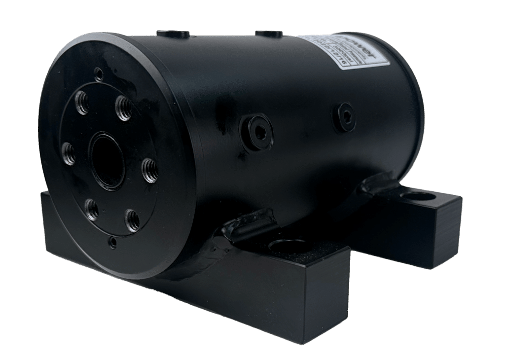
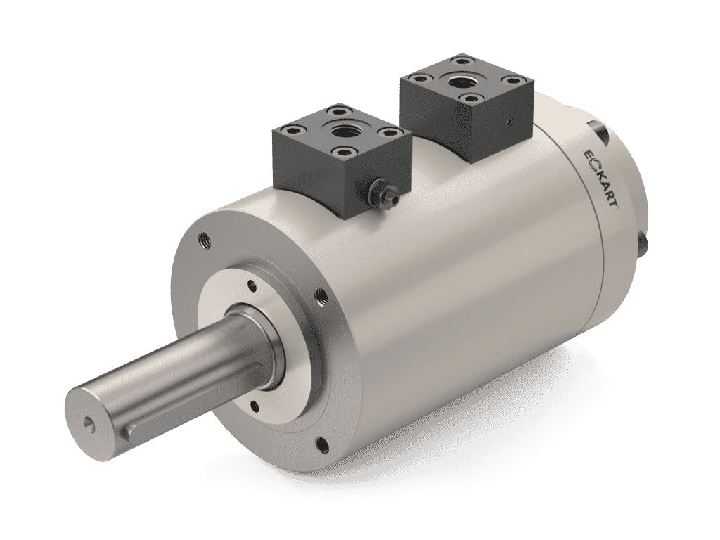
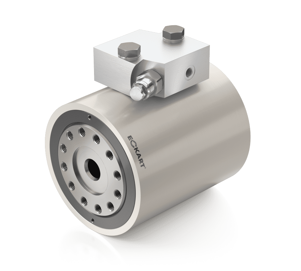
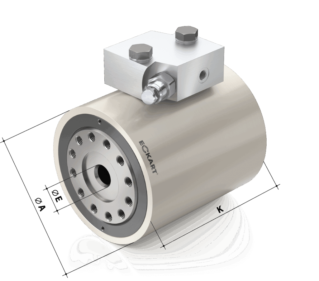
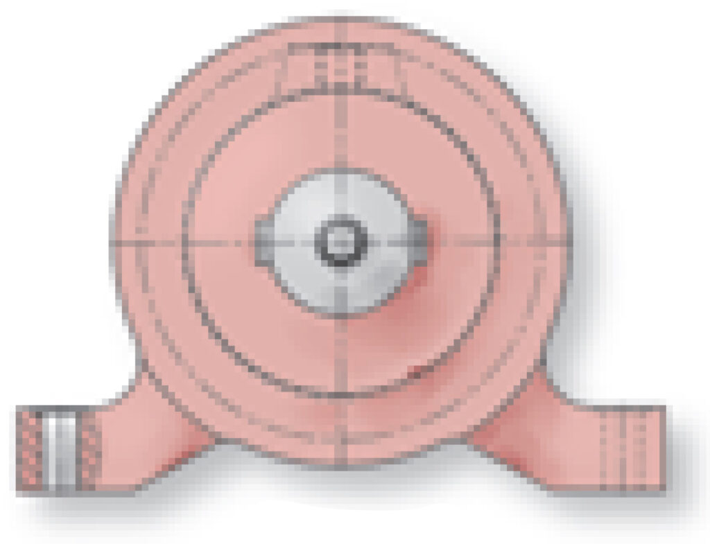
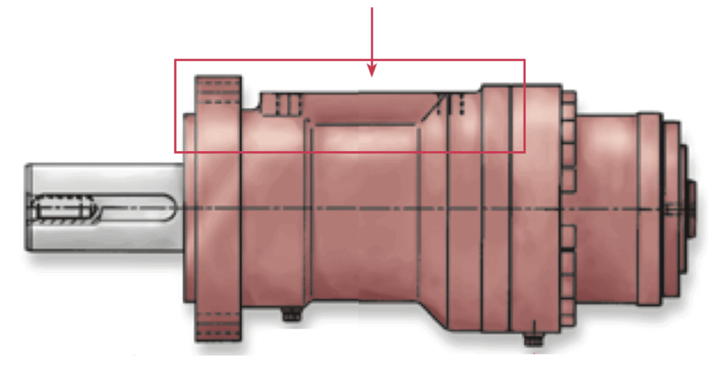
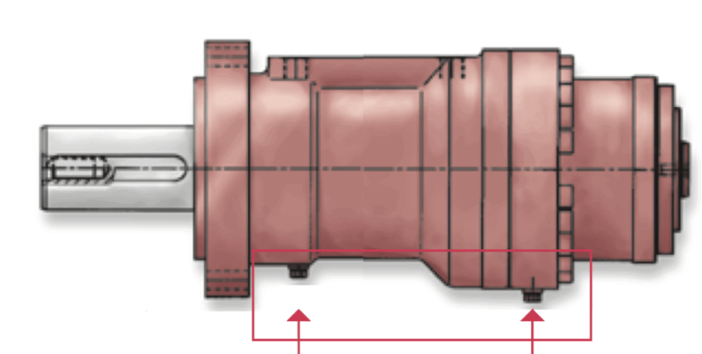
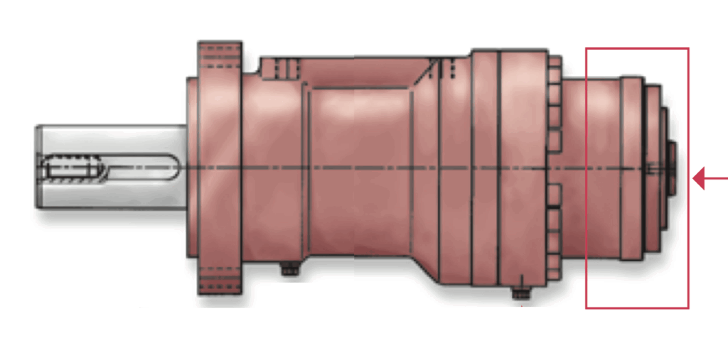
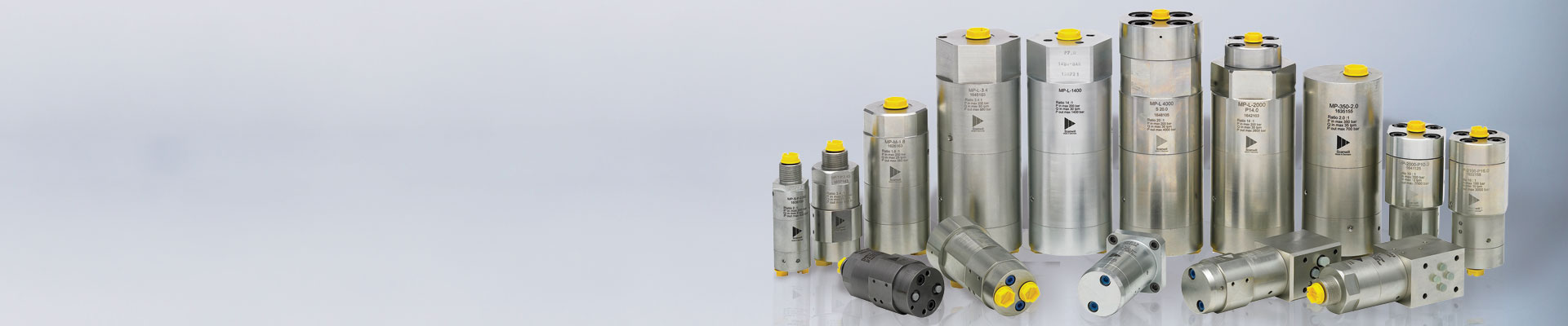
Hydraulic Pressure Intensifiers – MP-L Series
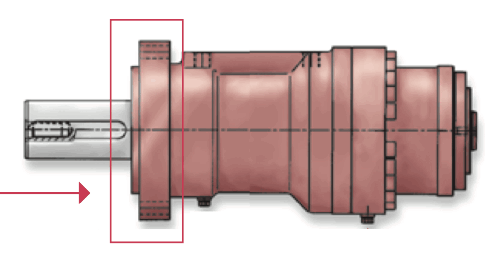
The MP-L Series is an in-line pressure intensifier designed for large hydraulic systems and features the highest inlet flow rating in the MP Series.
Key Features of the MP-L:
Technical Data:
Intensification Ratio Chart:
| Ratio | Min. Inlet Flow | Max. Inlet flow | Outlet Flow Q1 | Outlet Flow Q2 | Min. Inlet Pressure | Max. Supply Pressure | Max. Output Pressure |
| (i) | (GPM / LPM) | (GPM / LPM) | (GPM / LPM) | (GPM / LPM) | (psi / bar) | (psi / bar) | (psi / bar) |
| 2 | 15 / 4 | 13.22 / 50 | 1.32 / 5 | 0.52 / 2 | 218 / 15 | 2,900 / 200 | 5,800 / 400 |
| 3.4 | 15 / 4 | 21.16 / 80 | 4.71 / 17.8 | 3.44 / 13 | 218 / 15 | 2,900 / 200 | 9,860 / 680 |
| 4 | 15 / 4 | 21.16 / 80 | 3.89 / 14.7 | 2.91 / 11 | 218 / 15 | 2,900 / 200 | 11,600 / 800 |
| 5 | 15 / 4 | 21.16 / 80 | 3.06 / 11.6 | 2.33 / 8 | 218 / 15 | 2,900 / 200 | 11,600 / 800 |
| 7. 0 | 15 / 4 | 21.16 / 80 | 2.22 / 8.4 | 1.67 / 6.3 | 218 / 15 | 1,653 / 114 | 11,600 / 800 |
ScanWill is a supplier and pressure intensifier manufacturer for various applications including construction, mechanical, marine, and industrial.
Related Products
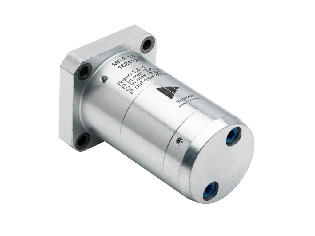
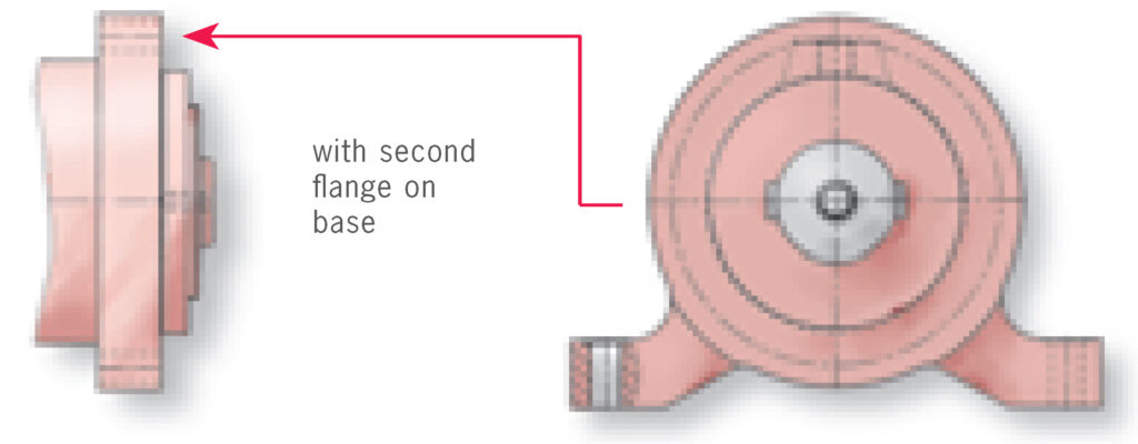
Hydraulic Pressure Intensifiers – MP-F Series
The MP-F Series offers flange mounted pressure intensification.
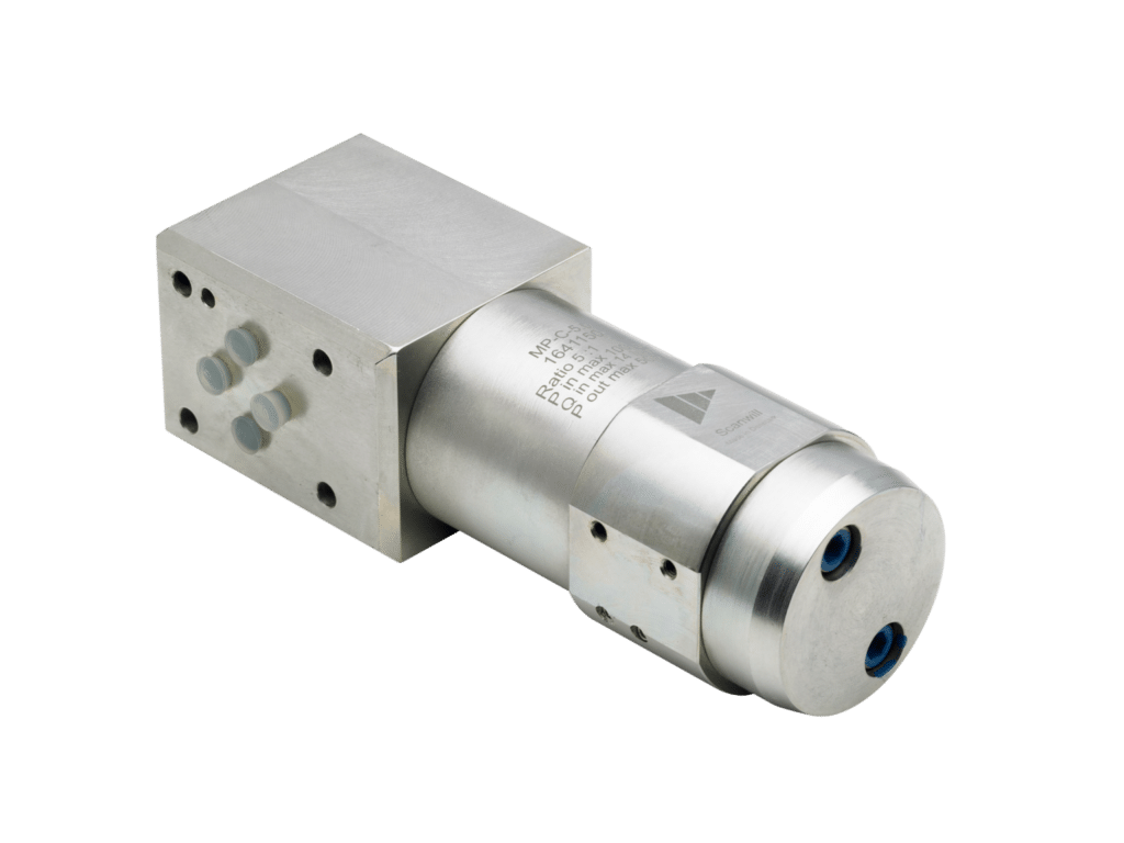
Hydraulic Pressure Intensifiers – MP-C Series
The MP-C Series offers cetop DO3 / NG6 mounted pressure intensification.
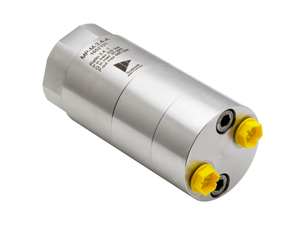
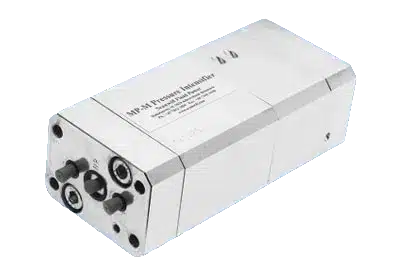
Hydraulic Pressure Intensifiers – MP-M Series
The MP-M Series offers an in-line pressure intensification solution with higher inlet flow rating of up to 35 lpm (9.3 gpm).
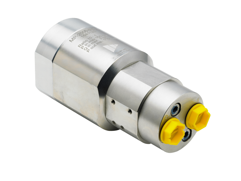
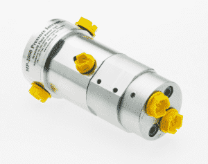
Hydraulic Pressure Intensifiers – MP-2000 Series
The MP-2000 Series offers an in-line pressure intensification solution with higher intensification ratios of 7.0 to 16.0.
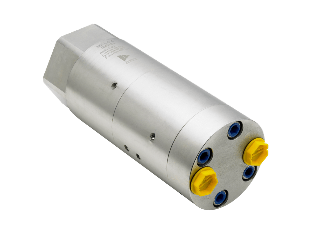
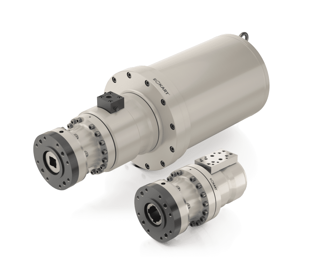
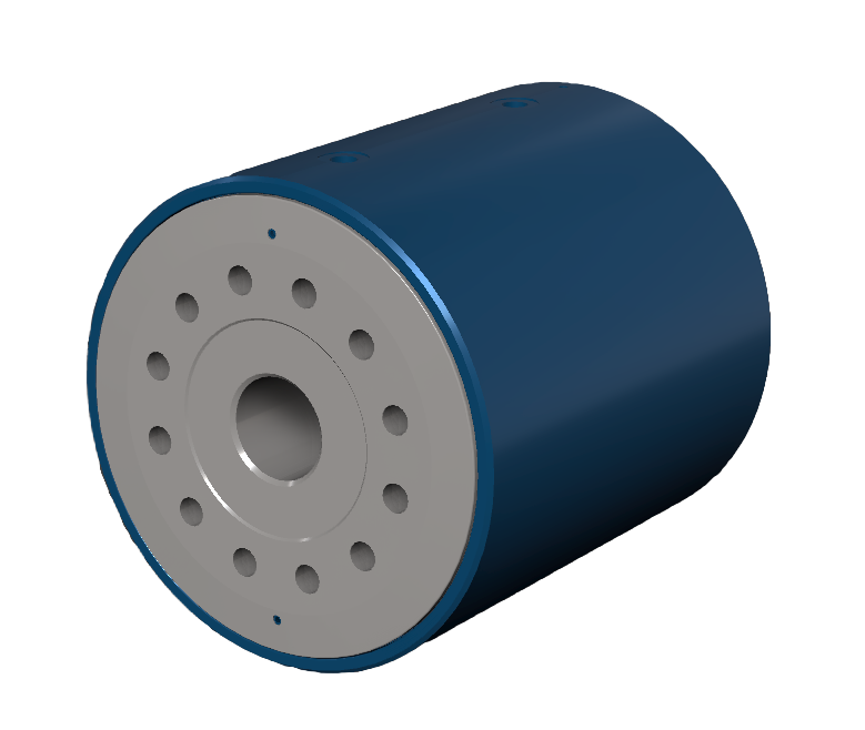
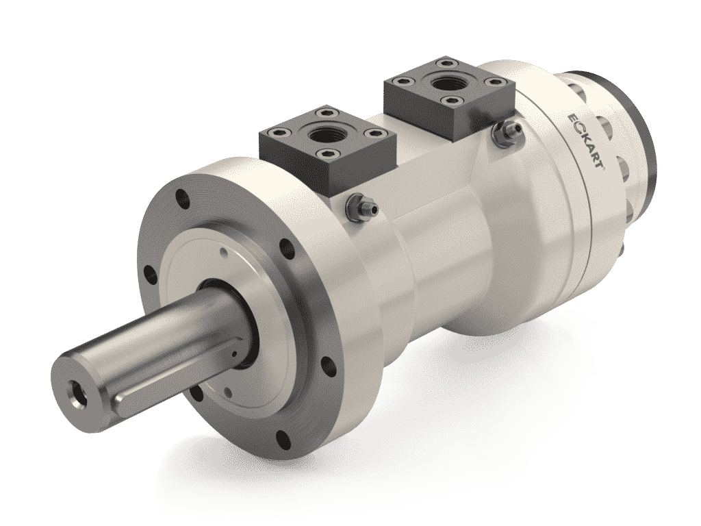
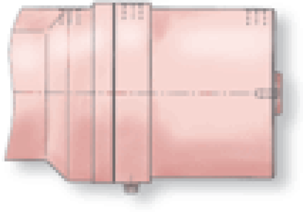
Hydraulic Pressure Intensifiers – MP-L Series
The MP-L Series offers an in-line pressure intensification solution with the highest inlet flow rating of up to 80 lpm (21.2 gpm).
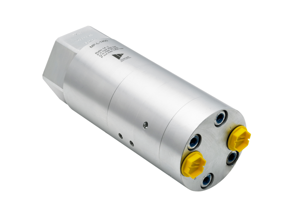
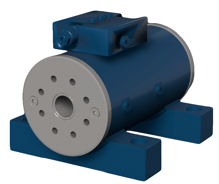
Hydraulic Pressure Intensifiers – MPL Series
The 1400/2000/4000 series models are hydraulic pressure intensifiers for high flow and high pressure.