Skip to content
hytroc logo

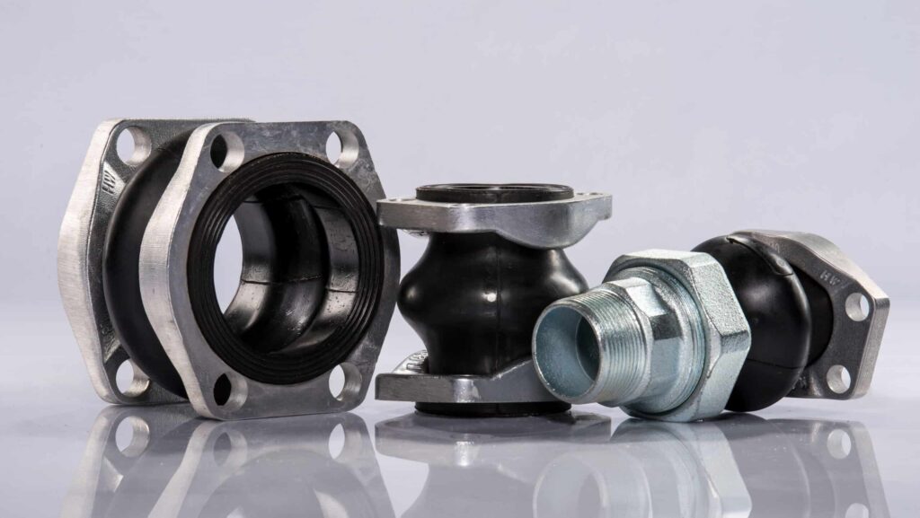
Hydraulic Rubber Compensators

Hydraulic rubber compensators dampen vibrations and noise, as well as axial and radial stress. Designed for low-pressure suction lines.

hydraulic rubber compensators for pipe alignment issues

Sizes 25-100 mm (1-4 inches) up to 116 psi (8 bar)


Need Support? We Can Help.


What Makes Us Different?

Fast lead times

Popular SAE flanged models in stock. Non-stock models are fulfilled within 6-8 weeks, or less with expediting available.

Limited market speciality

These designs are limited within the market. We are one of the few trusted suppliers.

On-demand experts

Our team stays responsive to your specifications and inquiries while ensuring fast lead times.


What are rubber compensators?

Rubber compensators, also known as elastic expansion joints, protect piping by absorbing movement in axial and radial directions. They also compensate for slight offsets and misalignment caused by natural settling or installation imperfections. Their flexible design preserves seal integrity, prevents component damage, and reduces the risk of leaks at connection points—ultimately improving system efficiency and extending service life.

How are compensators used?

Rubber compensators are installed between the reservoir and pump. They are typically used in high-vibration systems to prevent vibration transfer to the rest of the components and system. They are also useful in high-maintenance applications where frequent pump removals can cause misalignment between the pipes.

Compensator Benefits

  • Absorbs vibration, as well as axial and radial stress
  • Allows compression and elongation of pipes
  • Accommodates minor misalignment
  • Easily integrates with standard connections (SAE and DIN flanges)
  • Smooth, hydrodynamic design eliminates cavitation
  • Integrated vulcanized seals mean no additional sealing required
  • Built with reinforced high-strength NBR for a long service life

Before selecting a compensator, ensure your system is compatible with the maximum operating pressure rating of up to 116 psi (8 bar) and no more vacuum than 10.2 psi (0.7 bar).

1. Select the correct size/nominal diameter

The compensator size corresponds to the pipe’s internal diameter. Hytorc offers diameters ranging from 1 to 4 inches (25 to 100 mm). For example, if the measured diameter is 1 inch, a 1-inch (25 mm) compensator would be the appropriate choice.

2. Choose required end connections

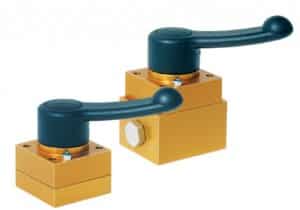
Compensators are designed for seamless integration into systems by using industry-standard flanges, such as SAE and DIN connections. The most popular mounting option is flanged threads, available in both aluminum and steel. Additionally, compensators can be equipped with threaded connections, made from steel. 

3. Consider fluid compatability

Ensure correct fluid compatibility to prevent degradation. Hydraulic compensators typically use NBR (nitrile butadiene rubber) for the internal surface material.

Common acceptable fluids include:

  •  Water-glycol
  •  Water-soluble oil
  •  Kerosene
  •  Jet fuel
  •  Diesel fuel
  •  Gasoline
  •  Petroleum-based fluids
 
We offer a wide range of acceptable mediums. For questions on fluid compatibility, message us at us@icfluid.com.


Compensators are essential in high-vibration systems and hard piping across industries like oil and gas, mining, marine, industrial manufacturing, construction, and transportation.

Construction and Mobile Equipment (Cranes, Trenchers, Drill Rigs)

All hydraulic systems, especially those in mobile applications, are subject to various movements and stress. Vibrations arise from regular operation of pumps and motors, while vibration from pressure and flow fluctuations can form due to varying changes of the load.

Mobile equipment, such as trench cutters, drill rigs, and cranes operate in rough terrains where the system itself faces constant jostling as it moves about its environment. This is why systems must employ some form of dampening component to protect the system. 


No.

These devices are only suited for pump suction line applications.

Compensators are primarily used for vibration isolation.

While offering some flexibility, compensators should not be relied on as a primary solution for addressing alignment issues.

Any fluid chemically compatible with NBR (nitrile butadiene rubber).

Hydraulic compensators can be used with any medium that is chemically compatible with NBR (nitrile butadiene rubber), the material used for the internal surface. For questions about acceptable mediums, please reach out to us@icfluid.com.

Popular models in stock. Non-stock items arrive in 6-8 weeks.
 
SAE flanged models are frequently stocked at our Ohio warehouse. For non-stock items, the lead time is 6-8 weeks, or less with expediting available.

Need More Help? Talk with a Specialist

hytroc logo

Hydraulic Check Valves

Check valves protect system integrity, prevent backflow, and save space. Hytorc’s half-ball seat design delivers a compact, economical solution rated for 10,000 psi (700 bar).

hydraulic in line check valves for industrial applications

Screw-in/drill or in-line models up to 10,000 psi (700 bar)


Need Support? We Can Help.


What Makes Us Different?

custom size blue icon

Compact installation height

The unique, half-sphere design maximizes space, especially in mobile hydraulics where every millimeter matters.

pressure gauge icon

Power up to 10,000 psi

While most competitors are limited 3,000 psi, our valves are engineered to meet the demands of high-pressure applications.

On-demand experts

Our team stays responsive to your specifications while ensuring fast lead times of 6-8 weeks.


What are check valves?

Check valves are a type of shutoff valve that block oil flow in one direction and allow it to flow freely in the other.

How are check valves used?

Check valves are essential for protecting pumps, actuators, and other components by ensuring pressurized fluid flows only in the intended direction. Ball check valves use a sphere that moves in response to fluid pressure. When fluid moves forward, the ball is pushed away from the valve seat, allowing flow. If flow reverses, the ball returns to the seat, sealing the valve and preventing backflow. This mechanism helps maintain system pressure, prevent contamination, and ensure efficient operation in almost every application.

Check Valve Benefits

  • Saves space with a specially treated half-ball seat
  • Manufactured with a high-tensile hardened and polished ball, allowing for a better fit in the seat, more uniform flow over the ball, and overall longer service life
  • Superior sealing surface with a machine radius matching the contour of the ball, meaning reduced contamination through a larger sealing surface that improves over time
  • Capable of 10,000 psi (700 bar) for high-pressure applications

Verify that the selected valve is rated for your system’s pressure. Hytorc can accommodate up to 10,000 psi (700 bar).

1. Determine required flow rate

The flow capacity determines the nominal size of a valve. Selecting the right size ensures optimal performance and avoids issues like inefficiency or equipment damage. 

For example: If your application requires a flow rate of 5 GPM, your selected valve would utilize a G ¼ or M14 x 1.5 thread.

Max Flow Rate (GPM)

Max Flow Rate (LPM)

Thread (BSP)

Thread (Metric)

Model Options

0.5–0.8

2–3

N/A

M6

RVA2, RVB2

1.1–1.6

4–6

N/A

M8X1

RVA3, RVB3

2.1–2.6

8–10

G1/8

M10X1

RVA4, RVB4, RVE4, RVF4, RVG4

4.7–6.6

18–25

G1/4

M14X1.5

RVA6, RVB6, RVE6, RVF6, RVG6

9.2–11.9

30–45

G3/8

M18X1.5

RVA8, RVB8, RVE8, RVF8, RVG8

15.9–18.5

60–70

G1/2

M22X1.5

RVA10, RVB10, RVE10, RVF10, RVG10

23.8–26.4

90–100

G3/4

M27X2

RVA16, RVB16, RVE16, RVF16, RVG16

2. Select valve type

Hytorc valves are available in two primary configurations: screw-in and in-line (cage) designs. Both of the following flow direction options are available for each type:

  • Screw-in direction closed: Blocks oil flow when installed, permitting flow only in the opposite direction
  • Screw-in direction open: Allows unrestricted oil flow in the screw-in direction

Use the widget tool below to find the right check valve type for your application.

Check Valve Type Selector Widget

Screw-in Mounting

Drill Mounting

In-line Mounting

Port A to B (Model)

RVA

RVA

RVE, RVG*

Port A to B (Graph)

*Internal threads on both ends

Port B to A (Model)

RVB

RVB

RVF

Port B to A (Graph)

3. Consider material

Consider the fluid being used and the operating environment to determine the material. Check valves are available in steel or stainless steel, with stainless steel being the preferred choice for applications exposed to moisture, high pressure, high temperatures, and aggressive fluids.

Additional factors

After selecting the size, type, and material, a model can be selected. For proper installation, please follow the manufacturer’s recommended specifications for cracking pressure and apply the correct tightening torque. These installation details are available on the specification’s page.


Check valves are used across a wide range of industries to ensure unidirectional flow and prevent back flow in hydraulic systems. From heavy machinery and agriculture to aerospace, marine, and energy sectors, these valves support critical functions like lifting, steering, braking, and pressure control in demanding environments.

Mobile Equipment (Tractors, Excavators, Cranes)

Check valves control flow and prevent backflow in nearly every industry. In applications like tractors, cranes and excavators; hydraulic components must integrate seamlessly into tight spaces. Compared to traditional valves, Hytorc has created a unique, half-sphere design, reducing the overall height to minimize space, and an optimized seat for superior sealing.

High-Force Applications (Spreaders and Cutters)

The power-to-size ratio is key when designing hydraulic tools for demanding environments. While most components typically handle up to 3,000 psi, Hytorc check valves enable spreaders and cutters to achieve 10,000 psi without sacrificing in compactness. The capability to generate more force while maintaining a small profile allows for greater mobility and ease of use, especially in rescue operations where lightweight, maneuverable tools are essential.


6-8 weeks, or sooner.

Check valves are made to order and can be delivered within 6-8 weeks with optional expedited shipping available if needed. Hytorc also keeps some inventory on hand for small shipments.

Yes.

Hydraulic check valves are designed to be used with hydraulic oil, but may be used with other mediums, such as water glycol. For questions about fluid compatibility, email us at us@icfluid.com.

Grade 303.

Hytorc check valves use an austenitic stainless steel, 1.4305 (303) grade.

10 pcs.

The minimum order quantity for our check valves is 10 pcs.

Need More Help? Talk with a Specialist

hytroc logo

Butterfly Valves

Hytorc butterfly valves save time for the technician working on the hydraulic system by not having to drain the reservoir. Designed for low pressure pump suction lines up to 230 psi (15 bar).

hydraulic butterfly valves shut off valves thin profile mobile application

Sizes 32-125 mm (1.25-5 inches) in aluminum with NBR seals


Need Support? We Can Help.


What Makes Us Different?

custom size blue icon

Save valuable space

Lightweight, compact, and easy to install—butterfly valves outperform ball valves in mobile systems.

person icon

No draining of reservoir

With the tank isolated, routine maintenance can be streamlined by not having to drain the reservoir beforehand.

innovative icon

28% more oil volume

Compared to ball valves, butterfly valves optimize flow efficiency without increasing component size.


What is a butterfly valve?

Butterfly valves, also known as shut off valves, are 90°, quarter-turn valves used for regulating flow. When installed at a tank outlet, flow can be shut off without draining the reservoir. 

Butterfly valves vs ball valves

In mobile applications where ball valves struggle to fit within design constraints, butterfly valves serve as an effective solution. Shut off valves offer a shorter and lighter profile. As the pipe size and nominal diameter increase, the space and weight advantages of butterfly valves become even more pronounced.

For a 1.25” pipe, butterfly valves are 63% shorter and 50% lighter than a ball valve.

Butterly Valve

Ball Valve

Length

1.4 in (35 mm)

3.7 in (95 mm)

Weight

1.1 lbs (0.5 kg)

2.2 lbs (1 kg)

On a 4″ pipe, those benefits scale dramatically, with butterfly valves measuring nearly 77% shorter and 71% lighter.

Butterly Valve

Ball Valve

Length

1.7 in (42 mm)

7.4 in (190 mm)

Weight

3.4 lbs (1.57 kg)

12.3 lbs (5.56 kg)

How does a butterfly work?

Hydraulic shut off valves are composed of a disk, stem, and body for precise flow control. The disk is the flow control element that pivots on the stem housed within the valve body. In the open position, it aligns with the flow direction to minimize resistance. When closed, it seals against the valve seat to prevent flow. A locking mechanism ensures the valve remains in the desired position during operation. Optional limit switches enable remote position monitoring for automating system diagnostics and control.

Butterfly Valve Benefits

  • Provides rapid shutoff in case of an emergency
  • 28% more flow compared to a ball valve of the same size
  • Saves time on maintenance by not needing to drain the reservoir
  • Aluminum body creates weight savings and corrosion resistance
  • Minimum stem design maximizes flow and reduces cavitation
  • Available with a limit switch for remote monitoring and automation

Butterfly valves are designed for low-pressure suction lines, that handle up to 230 psi (15 bar). Choosing the right model depends on critical factors such as the valve size, mounting style, and position control.

1. Select the correct size/nominal width

Start by measuring the pipe’s internal diameter to select the appropriate valve size. Hytorc shut off valves range from 1.25 to 5 inches (32 to 125 mm), ensuring compatibility with various systems. 

2. Determine mounting style

Butterfly valves can be mounted directly onto the hydraulic reservoir with a welded flange, conforming to the typical SAE J518 standard. 

While not required, it is recommended to install butterfly valves with a compensator for added protection and alignment. This is achieved by incorporating bushings into the valve assembly. The bushings let you mount the shut-off valve to an SAE connection. They screw into the SAE flange, adapting its thread size to match the fixing screws.  

Alternatively, if the reservoir flange is already tapped correctly, bushings aren’t required. 

3. Consider a limit switch

A limit switch prevents the hydraulic pump from activating when the valve is closed. If connected to PLC controls, this feature protects equipment by preventing the pump from running dry. 

All Hytorc valves are preinstalled with a cam, allowing a limit switch to be equipped at any time with just two screws. 


Hydraulic butterfly valves are commonly used on low-pressure suction lines across many industries, including naval, automotive, forestry, construction, wind energy, and aerospace.

Forestry and Recycling (Horizontal grinders)

Horizontal grinders play a critical role in forestry and environmental recycling, handling everything from land clearing and mulch production to biomass processing and construction debris. In these applications, hydraulic systems must be equipped with fail-safe mechanisms to prevent fluid loss. As one functional benefit, butterfly valves serve as emergency shutoff devices, minimizing the risk of oil spills when hoses or other hydraulic components fail.

By automatically sealing off flow, these valves help protect both equipment and the surrounding environment due to reduced oil volumes being leaked. This is especially vital given the diverse operating environments of horizontal grinders, which often include sensitive ecosystems and waterways. Just one gallon of oil can contaminate a million gallons of water—consider that against a 70-gallon hydraulic tank, and the stakes become clear.


Butterfly valves are typically in stock at our US warehouse. Backorders ship fast and are fulfilled in 6-8 weeks with additional expediting available if needed.

Easily.

All Hytorc butterfly valves are preinstalled with a cam, so you can add a limit switch anytime with just two screws. No modifications are needed.

Depends on your pipe’s nominal diameter.

The right valve size depends on your pipe’s nominal diameter. Hytorc offers butterfly valves from 1.25 to 5 inches (32 to 125 mm) to fit various setups. See more information on how to choose the correct valve.

Need More Help? Talk with a Specialist

10,000 PSI Valves

Manual Valves, Directional Control Valves, and Relief Valves for 10,000 psi (700 bar)

Hydraulic Servo Valves

Introducing a new generation of servo valves that deliver exceptional performance and precision, without compromise to cost, efficiency, and industrial reliability.


World’s smallest direct drive valve weighing less than 0.64 lbs (300 g), flow up to 5 gpm (18 lpm).

Ultimate power density weighing 1.21 lbs (550 g) with flow up to 16 gpm (60 lpm).

Most efficient direct drive valve for high flow applications from 13 to 66 gpm (50 to 250 lpm).

The next evolution in high-performance, high-flow valves from 66-174 gpm (250-660 lpm).


Need Support? We Can Help.


What Makes Us Different?

Setting new standards in performance

Patented additive manufacturing and compact electronics create new standards in power density, performance, and reliability.

Repeatable and reliable results

78% faster step response than traditional two stage valves with low hysteresis, null shift and threshold.

Major energy and emissions savings

$400 in annual energy savings per valve compared to a typical two stage valve.


Comparing Leading Valve Designs

Two-Stage Servo Valves

Two-stage servo valves, or mechanical feedback valves, are valued for their compact size and excellent dynamic performance, including fast response times and high-frequency capabilities. However, they come with limitations. The small orifices and high-pressure seals that help maintain performance can also make them more susceptible to contamination and blockages, especially if operated in harsh environments. Additionally, because they lack onboard electronics, they do not deliver the same level of repeatability and accuracy as modern direct drive valves.

Direct Drive Valves

Direct drive valves utilize an electrical feedback design. Contamination and hysteresis occur less frequently with direct drive valves making them more durable for demanding industrial applications. However, this comes with trade-offs in performance and size. Direct drive valves are generally heavier and bulkier in design, with slower step and frequency responses compared to two-step valves. This makes them less suitable for high-performance applications where dynamic response is critical.

Domin Valves

A Domin valve is a considered a servo proportional valve, a hybrid between two-stage servo valves and direct drive valves. Domin merges the benefits, such as the performance, efficiency, precision, and compact size from both without needing to compromise. Domin’s S6 Pro, for instance, offers an unmatched balance of performance and efficiency, boasting a 78% lighter design, a 67% faster response, 340% higher bandwidth, and 73% higher maximum flow compared to an equivalent direct drive valve.


Modern Electronics

Slim, on-board electronics replace outdated bulky centralized systems. This improves control, data processing, and communication capabilities while reducing the overall size.

  • Advanced and modern control systems, data processing, and analysis
  • Improved connectivity for remote diagnosis
  • Accurate position sensing
  • Compact design, located within the valve’s housing
  • Better security with fewer failure prone components

Modern Design and Simulation

Modern design and simulation technologies streamline development, enabling rapid iterations and faster decision-making and production processes.

  • Skip prototyping phases, iterating up to 10x faster
  • Simulation tools, such as CFD, help identify the optimal flow galleries to reduce pressure drops and maximize flow rates.
  • Advanced algorithms to optimize high step input speeds and frequencies and minimize overshoots while maintaining precise, repeatable control

Magnetic, Hall Effect Sensors

Hall effect sensors provide a more efficient and precise method of measuring position compared to traditional linear transducers. By utilizing magnetic fields, these sensors offer exceptional accuracy in both linear and rotary applications while significantly reducing size and weight.

  • 1% of the size and weight of conventional transducers
  • Enhanced real-time monitoring and adaptive control
  • Reduced energy consumption and optimized performance

Advanced Motors

Domin valves are equipped with brushless DC motors, offering superior precision and efficiency over traditional solenoids and limited-angle torque motors. These motors provide consistent performance without the wear issues associated with brushes, leading to longer life and reduced maintenance.

  • Consistent rotation and precise control over speed and position
  • No brush wear, resulting in extended motor life
  • Reduced maintenance needs compared to solenoids

Metal 3D Printing

This patented manufacturing process surpasses the limitations of subtractive machining, allowing the creation of lightweight structures through optimized material distribution and the removal of excess material.

  • Reduced material waste—up to 95% of material used in final product
  • Seamless integration of custom modifications like valve sizes, shapes, and flow characteristics.

Exceptional Precision and Accuracy

  • Fast step response: Domin delivers up to 78% faster step responses compared to a typical two-stage valve.
  • Low hysteresis: The low hysteresis of Domin valves ensures high accuracy of movement in both directions, as well as low null shift and threshold. For a two-stage valve, Domin can achieve a 93% lower hysteresis.
  • High power density: Domin valves offer the size, mass, dynamic capabilities, and industry-leading power density of the most advanced two-stage valves.
  • Advanced technologies: Superior precision and response control are driven by advanced algorithms, modern electronics, and brushless motors.

Cost Savings and Efficiency

  • Lower maintenance: With fewer components at risk of failure, maintenance needs are reduced, translating to less downtime.
  • Compact size: Domin produces the smallest servo valves in the world, along with significant weight and space advantages for the rest of their product line.
  • Annual energy savings: Replacing a typical two-stage NG06 valve with a Domin valve can save $400 in energy costs and reduce emissions by 1 ton per valve each year.

Reliability and Durability

  • Built for tough environments: Domin valves are extremely rugged and can handle heavy vibration at high cycle rates.
  • Outstanding contamination resistance: The valve amplifies torque from the motor to the spool, offering exceptional resistance to contamination, which is critical for harsh industrial environments.
  • Fewer points of failure: The absence of high-pressure seals reduces the risk of leakage and valve failure.

1. Select valve model for application

First, choose the appropriate valve for your application. Domin valves have been designed to accommodate a wide range of flow rates and pressure conditions. The options include:

  • S4 Pro: excels in small, precision applications
  • S6 Pro: handles higher flows for demanding industrial needs and high performance
  • S10 Pro: built for high-flow, durable, and reliable performance in tough environments

2. Determine rated flow

Next choose rated flow. Flow range is between 0.2 to 66 gpm (0.5 to 250 lpm), all rated at a 1,015 psi (70 bar) pressure drop. For systems requiring high precision control, the rated flow can be tuned to the nearest decimal point within the range for near-exact performance.

3. Choose spool lap condition

The spool lap condition determines how the valve reacts to control inputs.

Standard spool lap conditions:

  • Axis cut: most popular option for consistent performance
  • Overlap: Options range from 3-10%. These options can be used to fine-tune the valve’s control characteristics, making it ideal for applications where precise responses to input changes are critical.
  • For other options, please inquire.

4. Select control method

Domin valves feature electrical feedback and onboard electronics to simplify integration into modern hydraulic systems. All that is needed is a 24V power supply and a standard input/output interface. The control method options allow for seamless integration with various control architectures, ensuring that the valve response precisely to electrical signals.

Control method options:

  • +/- 10 volts
  • 4 to 20 milliamps, providing flexibility to choose the option that best suits the current control system.
  • For other options, please inquire.

5. Choose electrical connector

Next, select the right connector. Industry-standard connectors are provided to ensure easy compatibility and simple integration with your existing infrastructure.

Common connector options:

  • 4-pin hard-mounted connectors
  • 6-pin plus PE connectors for added flexibility
  • Fly-in lead connectors
  • For other options, please inquire.

6. Does your system require an enable mode?

For systems requiring an enable mode, typically a simple yes or no option, these can be easily configured into the Domin valve.

This feature allows operators to control when the valve is active, improving both safety and flexibility.

7. Select fluid type

Domin valves operate with standard red oil, as it is the most common fluid type found in hydraulic systems. Custom solutions are available for specialized fluid requirements.

8. Choose seal material

Selecting the right seal material ensures that the valve operates properly, even in harsh and challenging environments.

Seal options:

  • Nitrile, popular option for oil resistance and durability
  • Viton, enhanced resistance to high temperature and aggressive fluids.
  • For other options, please inquire.

To minimize pressure drops and maximize flow.

Within the design process, we’re able to use simulation methods to identify the optimum flow channels and port patterns within the available space to minimize pressure drops and maximize flow through the valve. This approach enables us to create a product closely aligned to the optimized design.  
 
For a more detailed look, check out this video.

Domin valves are considered a servo proportional valve, a hybrid of two-stage valves and direct drive valves.
 
A servo valve is typically a two-stage mechanical feedback valve that offers great step response and frequency in a compact package. A proportional valve is a direct drive valve with electoral feedback. These valves are not as high performing in terms of dynamic performance but have very robust and reliable designs. Domin valves present a new approach to hydraulic technology, merging the best of servo valves and proportional valve capabilities without the compromise.
 
For a more detailed look, watch this video.

A wide range including testing and simulation, robotics, timber, and more!

Domin valves are suitable for multiple industries from testing and simulation to animatronics in small robotics to your harsh industrial applications in die casting and the timber industry.
 
To learn more, watch this video.

Upgrading is very simple.

Domin’s flexible configurations and standard port patterns (S01, S04, NG6, NG10) allow easy integration into existing hydraulic systems.
 
Learn more with this video.

Absolutely.

Domin valves are engineered to endure high shocks, intense vibrations, and extreme temperatures, ensuring robust, precise control across a valve’s entire lifespan, even in the toughest industrial environments.
 
To learn more, watch this video.

Need More Help? Talk with a Specialist

WITTE Tools

Witte has continuously perfected the screwdriver like no other manufacturer – with the aid of unrelenting innovation, maximum attention to ergonomic design, as well as high quality materials made in Germany. Shape, hand-picked materials, ergonomic design, workmanship and physics all combine here to make the perfect tool.

 We offer the option to return any product at your discretion at any time. Rest assured, your product will be replaced with no explanations needed with complementary shipping, free of charge.

 Flexible sales and branding concepts make it possible for us to supply individual packaging and designs for distributors or OEMs.

Witte Max Screwdrivers have been extensively tested by the Independent IGR Institute for Health and Ergonomics with regard to usability and ergonomics.


for wet and oily conditions

  • Matte, chrome-plated, and made of hardened and tempered special steel
  • Proven triangle shape for ideal turning angle of the hand (120°) 
  • Fast turning zone from soft material makes working comfortable 
  • Permanently marked blades to ensure fast and correct identification
  • Faster and more accurate turns for lower torque applications
  • Truncated phillips tip to fully seat fasteners without bottoming out
  • Handles are expertly molded around the shanks for a strong and precise fit

Electronical Engineering and Electronics

Ensuring peak accuracy at the point of contact with the screw — even at voltages up to 1000 volts, because every screwdriver is tested in a dip-tank up to 10,000 volts.

  • Safely insulated blades
  • Fast turning zone from soft material makes working comfortable and safe 
  • PRO Wittron line includes further developed geometry perfect for mechanical and electronic applications 
  • Good handling due to soft component surfaces

Professional Electronic Applications

Ergonomic, force and safety – the MAXX VDE gets best results in all disciplines. It is tested individually in a water bath at 10,000 volts which enables it to work with voltages of up to 1,000.

TEST POINTS AND TEST HOSE ASSEMBLIES

Test Points and Test Hose Assemblies

Pressure is one of the most important diagnostic parameters in the hydraulic circuit.  Obtaining pressure readings is essential to successful preventive maintenance and troubleshooting. The Spradow test points allow the connection of a pressure gauge in only seconds while the equipment is running. It is the safest, cleanest and most convenient way of measuring pressure. Designing your equipment with the Spradow test points will improve the quality of your equipment and in today’s market, higher quality makes the equipment more attractive to potential buyers. The spring loaded check valve inside the test point opens during engagement of the special micro-bore hose fitting end. The connection can be performed under pressure without the use of tools. A single gauge connected to the high pressure micro-bore hose can check an unlimited number of test points. We also offer various types of hose assemblies for direct connection to the test fitting.

Spradow is a supplier and test point and test hose assembly manufacturer for various applications including construction, mechanical, technological, and industrial.


Related Products

SERV-CLIP® HOT TAP CONNECTION

Serv-Clip® Hot Tap Connection

The Serv-Clip® tube measuring connection is used to add a test point on an existing hydraulic circuit within 3 minutes—no cutting of pipes, even if the system is pressurized to 9,100 psi (630 bar). Then carry out your measurements: pressure, flow rate, leakage, temperature, oil sampling or connect a variety of measuring devices.

Required tools for installation: 6mm allen wrench and jaw wrench SW22

Models: Serv-Clip® Type 1 (Installation on pressurized pipes):
Used for sensors with G1/4″ thread

Serv-Clip® Type 2 (Installation on non-pressurized pipes):
Used for sensors with G3/8″ thread

Diameters Available:

  • Metric: 10 – 42 mm
  • Tube: 3/8 – 2 inches (9.5 – 50.8mm)
  • Pipe: 1/4 – 3 inches (6.3 – 76.2mm)
  • Over 3 inches (88.9mm) with adaptor SC-XE-607

The flow rate and leakage sensor functions through the calorimetric principle and can be installed with the Serv-Clip tube measuring connection Serv-Clip® (type 2) in 5 Minutes without cutting pipelines and only requiring the pressure of the hydraulic system to be removed while the needle is piercing the pipe or tube and while the sensor is being installed. The output signal is 4 to 20mA and is calibrated according to your requirements. With the Flow Rate Sensor (from 0.164 to 16.4 feet per second or from 0.05 to 5 meters per second). The sensors are available in stainless steel and plastic covers:

  • Monitoring flow rate and wear of pumps
  • Operability of accumulators
  • Filter transmittance
  • Heat exchangers
  • Nozzle flow rate
  • Speed of hydraulic motors

With the Leakage sensor (from 0.164 to 16.4 feet per second or from 0.05 to 5 meters per second):

  • Seal damage and leakage identification

Watch the following videos for a demonstration of how the Serv-Clip is installed and utilized.

Serv-Clip® is a supplier and Serv-Clip® Hot Tap Connection manufacturer for various applications including construction, mechanical, technological, and industrial.


Related Products

Valve Actuators

A compact and high-torque way to open and close your valves, increasing performance, uptime, reliability, and safety while reducing maintenance costs using helical spline technology.

Valve Actuators

Valve actuators mount on valves and move valves to a desired position by utilizing liquid, electric or some other power source. Selecting the correct valve actuator will increase performance, uptime, reliability, and safety while reducing maintenance costs. Although the most common and important use of an valve actuator is to open and close valves, current actuator designs go far beyond the basic open and close function. The valve actuator can be packaged together with position sensing equipment, torque sensing, motor protection, logic control and digital communication capacity all in a compact, protected enclosure. Applications include: power plants, oil and gas, industrial, ships and chemical industries. Below is a listing of valve actuators available from IC-Fluid Power.

ScanWill logo

Hydraulic Pressure Intensifiers

Compact yet powerful, pressure intensifiers deliver a nearly instant pressure boost precisely when and where it’s required.


Hydraulic pressure intensifiers provide standard intensification ratios of up to 16 and yield maximum outlet pressures of 58,000 psi / 4,000 bar.

A tool intensifier is a safety device that intensifies the available pressure from your truck to power your 10,000 psi hydraulic tools.

Single-Stroke Cylinder Type pressure intensifiers allow the input fluid to be the same as, or different than, the output fluid.


Need Support? We Can Help.


What Makes Us Different?

Easily add pressure to existing systems

Increase output pressure from a low-pressure supply without major investments or upgrades.

Increase energy savings for the entire system

Add pressure only where and when needed. Using low-pressure components with an intensifier cuts down on operating costs.

Fast lead times of 1 to 2 weeks

1-2 week lead times, so that you can work faster. For cases with higher urgency, faster delivery may be possible.


Pressure Intensifiers MP 2000 XP Hydraulic

What are Pressure Intensifiers?

Reciprocating or single-stroke cylinder intensifiers are used to increase the pressure output of an existing low-pressure system, giving a boost of pressure when and where it’s needed, yielding greater pressure.

How are Pressure Intensifiers Used?

Pressure intensifiers are powered by a pump, which is operating at a set pressure. The hydraulic intensifier consistently delivers flow until the output pressure has been reached. The flow from the pump enters the intensifier, where two pistons of different sizes (respective to the intensification ratio) pump the fluid, thereby intensifying it. In the process, waste flow is returned to the tank.

Pressure Intensifier Benefits

  • Boost pressure from existing equipment
  • Avoid costly investments in machinery, such as an HPU or pump
  • Save space due to the intensifier’s simple, compact design
  • Use with standard industry pipe clamp
  • Choose from a large range of mounting options (in-line, flange-on, CETOP, etc.)
  • Increase energy savings and reduce carbon footprint

A hydraulic pressure intensifier can be used for many applications. These include rupture tests on hoses, pipes, and containers; hydroforming; bolt tensioning; presses; and proportioning precisely defined volumes. It is also useful for demolition tools, such as stone crushing tools and hydraulic construction tools. Additionally, it can be employed in hydraulic power packs and workholding cylinders.

Mobile Applications

In mobile applications, such as cranes, pressure intensifiers increase the pressure in the cylinders during retraction and ensure sufficient pressure within the stabilizer. The outlet pressures for this application include 3625 psi/250bar – 4350 psi/300 bar.

Pressure Testing

Pressure intensifiers can be used to provide test pressures for hydraulic components at 7250 psi/500 bar – 11,600 psi/800 bar, and for tubes and hoses for diesel engines (2,000+ bar). Pressure can be boosted from existing HPUs to negate having to buy an additional test pump.

Hydraulic Tools

Power hydraulic tools with a pressure intensifier connected to an existing power source. Intensifiers can boost pump pressure from as low as 1,450 psi/100 bar to an operational range of 4,350 psi/300 bar – 11,600 psi/800 bar.


No, pressure intensifiers are solely designed to intensify pressure.

Pressure intensifiers sacrifice flow for increased pressure and should not be used when needing simultaneously high flow and high-pressure outputs

Yes.

You can use water glycol with an intensifier, but the glycol concentration must be greater than 5%. For anything under 5%, a stainless-steel intensifier is required. Pressure intensifiers can be used with other fluids requiring special sealing. There are multiple sealing options, such as EPDM, Viton, etc. that can be selected for fluid compatibility.

Intensifiers are characterized by the desired pressure, inlet flow, and mounting style.

Selection is based on the maximum low pressure they can handle, along with any additional features specified by the application requirements. Follow our easy flow chart to see which intensifier you need. Help me choose an intensifier.

10 µm or better filtration.

Intensifiers have incredibly tight tolerances that they rely on for proper operation.

Yes.

Pressure intensifiers are available in stainless steel. Contact us to learn more.

No.

An intensifier is intended for applications that require pressure but not flow. If one is used in a pumping application, output flow will likely be unsatisfactory, and the intensifier will have a significantly reduced service life.

No.

An intensifier is an intensifiers and it is not a load-holding device. Despite containing built-in check valves, these are used for internal functions and are not designed to hold loads. If load-holding is required for your application, a separate load-holding device is needed.

Yes.

If the T-port is not connected, the intensifier will not function. The piston inside of the intensifier will not oscillate.

No.

Pressure intensifiers only work with fluids.

No.

Pressure intensifiers are not designed to hold loads despite having integrated check valves. If load-holding capabilities are needed, then appropriate valves such as load-holding valves should be used after the intensifier.

Yes.

However, a bypass circuit must be used so that the higher flows do not damage the intensifier. Click here for a diagram of a high pressure application. Click here for an example.

Yes.

If you’re not finding the right fit for your application, give our friendly engineers a call +1-419-661-8811 or send an email to sales@icfluid.com.

Need More Help? Talk with a Specialist