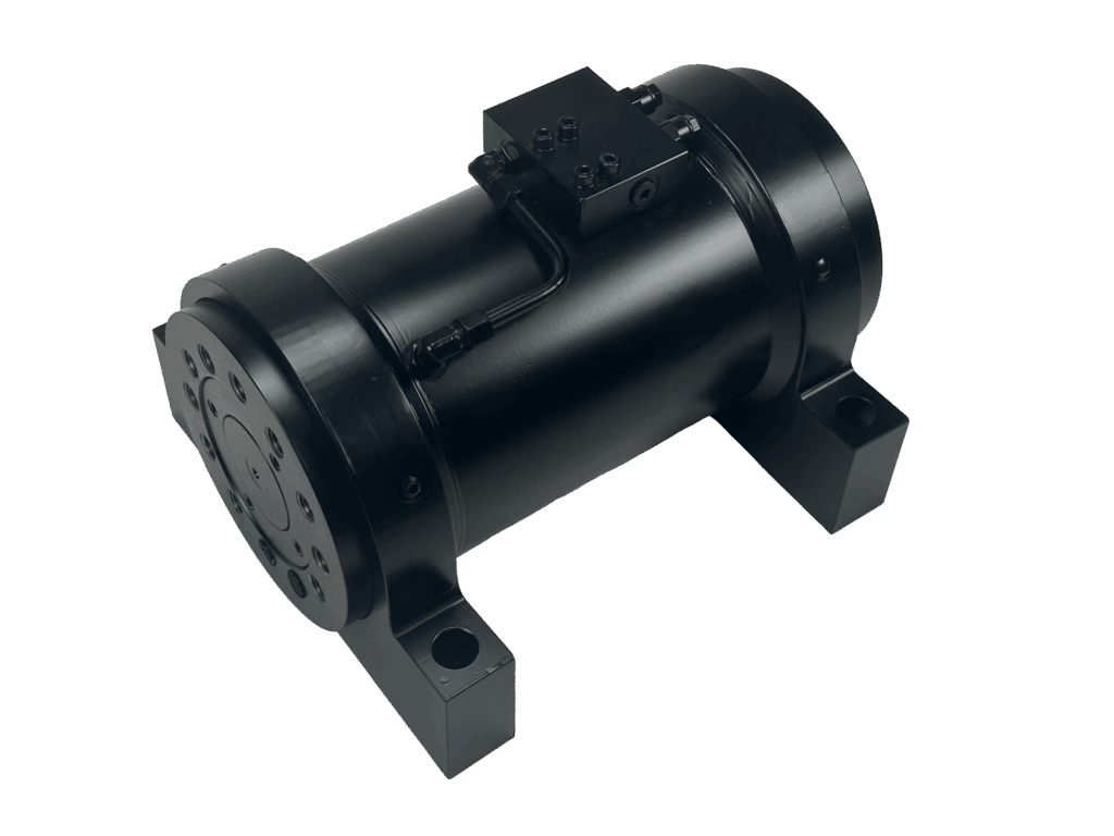
press products
Our high quality manufacturers provide products to help optimize the safety and efficiency of your press systems, including shock dampers (or impact dampers), rod-locking devices, hyla-lift die splitter cart, and more.
We offer a variety of specialty hydraulic cylinders for many industrial and mobile applications, including on and offshore oil industry, injection molding machines, locks and dams, steel industry, testing equipment and more. Cylinders are available in different types such as telescopic, servo cylinders high frequency oscillating, large bore, long stroke, etc.
One of the largest testing ranges in the market, offering lightweight models for static applications or high frequency cylinders for dynamic testing.
Standard Hydraulic Cylinders with a wide variety of standard dimensions, connections, and mounting options.
Rod Locking Devices are a safety holding device that prevents movement until released by hydraulic pressure.
Custom Cylinders can be specifically tailored to almost any requirements you can imagine.
100% made in Germany with incredible attention to detail to your exact specifications ensuring a perfect fit for your application.
Largest testing range in the marketing, offering lightweight servo actuators for static applications or high frequency cylinders for dynamic testing.
Bores adjustable to the millimeter, meaning your cylinder is built from a solid block of steel (320 series) including no leakage, long service life, and good data.
Test cylinders are used extensively in the testing sector and can be used for checking the functional safety of systems, component parts or products, for structural testing of airplanes, refrigeration compressors, automobile exhaust systems, or for simulating loads and movements, such as operational profiles and flight profiles.
Hydraulic Test Cylinders are used in a wide variety of applications including automotive testing such as lifecycle tests, aerospace system tests such as load and environmental condition simulation, and fluid power operating condition simulation.
Servo hydraulic lifecycle tests are the current industry standard for automobile components that are used far beyond safety-related structural elements. Users can depend on hydraulic test actuators for high positioning accuracy and reliability in applications for test systems and real time control. A test cylinder with a dynamic lift of up to 35 mm (1.3 in.), speed of 1.3 m/s (51.2 in/s), and acceleration of up to 50 m/s (1968.5 in/s) could be used for a test load requiring up to 28 kN (6,294 lbf) and a frequency up to 20 Hz.
System tests that simulate loads and environmental conditions in different flight phases are particularly demanding. To test the landing flaps and slats, servo hydraulic cylinders could be used here to replicate the airflow that involves rapidly changing forces with irregular parameters. For example, a servo cylinder with a bore between 40 to 160 mm (1.5 to 6.2 in.) could be used for a test stand with a holding force between 140 – 300 kN (31.4 to 67.4 lbf) and a stroke requirement of 300 to 1,670 mm (11.8 to 65.7 in.).
To determine the characteristic values of a seal, seal test benches are suitable for simulating a wide range of operating conditions. Double rod cylinders could be used here for fatigue tests focused on examining the frictional force of the seals, tightness on rods and shafts.
These hydraulic motors are provided by Jahns. The addition of this product range to their catalog gives them a greater manufacturing depth and guarantees a higher-level of product quality. The company utilizes CNC machining centers to manufacture products in small batches. All products are checked in their test facilities before they leave the plant.
Hydraulic flow dividers synchronize cylinders and motors. Gear flow dividers cover 95% of applications with errors as low as ±1.5–4%. Other options include flow divider valves (±4–5%), radial piston dividers (±0.5–0.8%), and volumetric dividers (zero error).
Flow rate: up to 58 gpm (219 lpm). Pressure up 4,600 psi (317 bar). Sync error: ±1.5 to ±4%. Available in 2 to 12 sections. Most popular model.
Flow rate: up to 145 gpm (548 lpm). Pressure up 3,500 psi (241 bar). Sync error: ±0.5 to ±0.8%. Available in 2 to 12 sections.
Flow rate: up to 79 gpm (298 lpm). Pressure up to 6,100 psi (420 bar). Sync error: nearly 0%. Available in 3 to 8 sections.
Flow rate: up to 39 gpm (150 lpm). Pressure up to 5,075 psi (349 bar). Sync error: ±4 to ±5%. Available in 2 sections only.
Flow Rate: 3.1 gpm (12 lpm). Pressure up to 3,045 psi (209 bar). Available in 2 sections only.
Precise synchronization: Accuracy as low as ±0 to 0.5% error for applications needing high precision
Fast lead times: Fast and flexible shipping. Standard lead times of 4-6 weeks with expedited delivery in less than one week.
Capable of handling bigger pressure differences between sections than other leading brands.
When you have multiple motors or cylinders connected to one pump, they cannot operate simultaneously because power is not evenly distributed to each component. Flow dividers simplify this problem by splitting the flow from one source into two or more output parts, which can be equal or unequal.
The most common designs include the gear-type and spool design. For applications requiring extremely high accuracy (greater than 99%), radial piston and volumetric designs work best.
Gear (2 to 12 sections): Gear flow dividers are a cost-effective way to divide flow without losing a large amount of energy or heat. Comparatively to spool dividers, these devices are more tolerant of contamination.
Spool (2 sections): This design relies on pressure compensation to divide flow and is limited to just two sections that can be split evenly, 50:50, or unequally. These are well-suited for applications where synchronization is flexible and complete accuracy is not a requirement.
Radial piston (2 to 12 sections): These are designed with high accuracy in mind, but have higher pressure drops than gear.
Volumetric (3 to 8 sections, 2 to 12 chambers): The volumetric design functions by volume dosage and the exchange between a volume synchronizer and working cylinders. The volumetric design is for high accuracy applications and has lower pressure drops compared to radial piston dividers.
Radial Piston Flow Divider
First, identify the following parameters to match performance and sizing with system demands. This includes:
Next, determine how much accuracy is required.
While flow dividers are precision components, some degree of synchronization error is normal. In short-stroke applications (where the cylinder travels a limited distance per cycle), a small percentage of error is often negligible and unlikely to affect performance. However, in long-stroke applications, even a small percentage of synchronization error can accumulate across the full cylinder travel, potentially leading to misalignment, uneven load sharing, and increased mechanical stress.
Gear flow dividers are the standard choice for general operations. For applications demanding higher precision, consider radial piston or volumetric dividers. Divider valves can be used for applications that allow lower accuracy.
Only for 2 flows/sections. Compact, economical model. Accuracy between ±4–±5%.
Most popular and cost-effective model. Accuracy between ±1.5–±4%.
Tighter tolerances than gear models with larger pressure drops, accuracy between ±0.5–0.8%. Input flow rates starting at 13 gpm (50 lpm).
Highest precision model, designed for applications requiring near perfect accuracy (no error).
The chart below compares synchronization accuracy across different models of flow and volumetric dividers.
The first ring splits dividers into groups: flow (light blue) and volume (dark blue). The second ring shows the type of divider. Flow dividers options include divider valves, gear, and radial piston while volumetric dividers include multi-chamber and linear stroke designs. The outer ring lists specific series models with their synchronization error.
As you follow the chart clockwise, accuracy improves with the level of error decreasing. For example, the MKA and MKS divider valves have an error of 4–5%. The next model, HTO gear divider, has better accuracy with errors as low as 3-4%.
Choose your flow divider series based on sections, flow, and pressure. Then, refine by synchronization accuracy.
Series 174_97d678-fc> |
Model 174_61f72e-db> |
Material 174_cc39c9-e5> |
Sections 174_120e56-b1> |
Flow Rate 174_18a259-76> |
Pressure 174_3fe631-13> |
Sync Error 174_76da6b-da> |
Divider Valves 174_03a9ae-fc> |
MKA 174_94c214-73> |
Aluminum 174_0ffe0b-2f> |
2 174_1d17ba-3c> |
0.53 up to 39 gpm |
3,045 psi (210 bar) 174_49963e-d7> |
±4 – 5% 174_a111d7-ad> |
Divider Valves 174_2231e3-1d> |
MKS 174_a4be4e-40> |
Steel 174_e3a17f-af> |
2 174_6a283e-a0> |
0.53 up to 39 gpm |
5,000 psi (350 bar) 174_ab05a6-87> |
±4 – 5% 174_92f046-0f> |
Gear 174_cce506-05> |
MTO 174_8b32c8-41> |
Aluminum 174_e9ca3e-e3> |
2 to 12 174_5f8231-a1> |
16 gpm (60 lpm) 174_34ea2f-cb> |
3,625 psi (249 bar) 174_a88d60-5c> |
±1.5 – 2% 174_687e5c-65> |
Gear 174_596105-4f> |
MTO 174_859ad3-38> |
Cast Iron 174_a3a1c1-20> |
2 to 12 174_19e359-d5> |
58 gpm (219 lpm) 174_181ccd-65> |
3,900 psi |
±3 – 4% 174_a4cfce-24> |
Gear 174_83bdcb-ae> |
HTO 174_058f73-f3> |
Cast Iron 174_015ce6-d2> |
2 to 12 174_9bd38e-e8> |
37 gpm (140 lpm) 174_269658-41> |
4,600 psi (317 bar) 174_ceb6f7-0c> |
±3 – 4% 174_a6326d-80> |
Radial Piston 174_e599e9-26> |
MTL 174_917123-08> |
Steel 174_770521-3d> |
2 to 12 174_0769b2-3d> |
66 gpm (249 lpm) 174_684628-a7> |
3,500 psi (317 bar) 174_5b43ae-f0> |
±0.5 – 0.8% 174_0980ed-ec> |
Radial Piston 174_09503d-54> |
STL 174_1064c6-0f> |
Steel 174_d91eb0-30> |
2 to 12 174_0d604a-a6> |
105 gpm (397 lpm) 174_037a9b-ba> |
3,500 psi |
±0.5 – 0.8% 174_8b607e-09> |
Radial Piston 174_51b827-59> |
MT-GM 174_9ac039-c8> |
Steel 174_3b68b2-b9> |
2 to 12 174_b56d65-03> |
145 gpm (548 lpm) 174_aee3f5-65> |
3,500 psi |
±0.5 – 0.8% 174_a20c56-d8> |
Volumetric 174_e3217e-64> |
MLH 174_b57ad9-4a> |
Steel 174_c5f053-47> |
3 to 8 174_9d67e7-56> |
50 cm³ up to 12,300 cm³ (3.1 in³ up to 750.6 in³) 174_b17f92-bf> |
3,600 psi |
No sync error 174_a0fcdb-31> |
Volumetric 174_a39096-0e> |
MZB 174_675480-10> |
Steel 174_4f55ca-f2> |
2 to 12 |
79 cm³ up to 40,000 cm³ (4.8 in³ up to 2440.9 in³) 174_c46b45-7b> |
3,600 psi (241 bar) or for special builds 6,100 psi (420 bar) 174_c82567-3d> |
No sync error 174_b5be4a-f6> |
Some common applications include synchronizing fluid motors and hydraulic cylinders, and intensifying pressure in hydraulic pumps. Our flow dividers are available with or without pressure relief valves to protect hydraulic systems from excessively high pressures.
In the case where multiple cylinders need to move something in sync, flow dividers offer a great solution. This is useful, for example, in lifting platforms, where the platform must remain level to prevent binding in the guiding mechanisms as well as for the objects on top of the platform.
Flow dividers can be utilized as a pressure multiplier. This type of hydraulic circuit can be used where a low-pressure circuit is already in use and where there is only need of high-pressure flow.
This is achieved by adding an extra section of equal or greater displacement to the flow divider. The return line of this section is connected directly to tank so that it in effect works as a motor for the other sections thereby increasing their outlet pressures.
Customize a hydraulic rotary actuator to your application or replace it with a drop-in model. Choose from our high-quality, German made actuators or fast, reliable replacements designed for leading brands like Helac.
Eckart rotary actuators custom-designed to meet specific needs, hydraulic rotary actuators provide durability and dependability.
IC Series rotary actuators are compact hydraulic actuators with high torque and bearing capacity with short lead times and flexible shipping methods.
Helical gear rotary actuators are designed with space in mind and are suitable for many applications needing a compact solution.
The IC Series can be used as a drop-in replacement to Helac’s rotary actuators and offers quick lead times of 20-26 weeks (or 10-14 weeks with expedited shipping.)
70% of Eckart’s rotary actuators are custom-designed to meet customer needs. Tell us your application and we will present you with an optimal solution.
Refer to the chart below to find the correct model based on pressure, rotation, and torque.
For more help choosing an Eckart rotary actuator, go to How to Choose an Eckart Rotary Actuator.
Model | Pressures | Max Torque | Sizes | Rotation |
SM4 (Most popular model, custom options) | 3,625 psi (250 bar) | up to 2,200,000 Ibs-in (250,000 Nm) | 13 standard sizes, custom | Standard rotation: 90°/180°/270°/360° Custom and intermediate angles |
E1 (Standard model with custom options) | 1,450 psi (100 bar) | up to 22,000 lbs-in (2,500 Nm) | 5 standard sizes, custom | Standard rotation: 90°/180°/270°/360° Custom and intermediate angles |
E3 (Standard model) | 3,045 psi (210 bar) | up to 31,800 lbs-in (3,600 Nm) | 5 sizes | 180°, 360° |
Model | Pressures | Max Torque | Sizes | Rotation |
IC10 | 3,045 psi (210 bar) | up to 23,890 Ibs-in (2,700 Nm) | 6 sizes | 180°, 360° |
IC20 | 3,045 psi (210 bar) | up to 37,170 Ibs-in (4,200 Nm) | 5 sizes | 180° |
IC30 | 3,045 psi (210 bar) | up to 212,410 Ibs-in (24,000 Nm) | 8 sizes | 180°, 360° |
IC40 | 3,045 psi (210 bar) | up to 59,290 Ibs-in (126,650 Nm) | 3 sizes | 200°, 220° |
In its simplest form, a hydraulic rotary actuator is a device that uses hydraulic fluid to generate rotary motion without a linkage. These devices come in handy when applications call for any form of transporting, securing, or positioning of parts.
In terms of design, hydraulic rotary actuators are most often configured as vane type, rack-and-pinon type, or helical spline actuators.
IC-Fluid Power’s rotary actuators are the helical spline design. This means, a piston and a helix, or sliding spline, work together to convert the linear motion of the piston into rotational motion. Helical spline actuators function when the piston is axially displaced using hydraulic pressure causing simultaneous rotation of the piston.
Hydraulic rotary actuators are typically designed to operate at low speeds and produce high torque through arc lengths ranging between 90°, 180°, 270°, and 360°. They also can be configured up to 720° or more by making the spline gears longer while maintaining the same diameter.
Different actuator models typically depend on the system’s operating pressure. This is why it’s important to know the pressure required, along with other key factors including load capacity, rotation angle, rotation speed, and more.
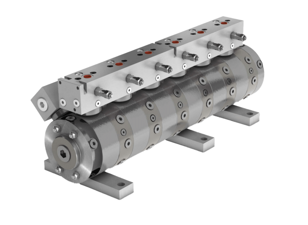
First, determine the operating pressure. This is important to ensure the actuator is rated for the system pressure being used.
The amount of torque helps determine how the actuator will perform and how much it can handle, especially in terms of load capacity. The higher the torque output, the more load capacity the device will have.
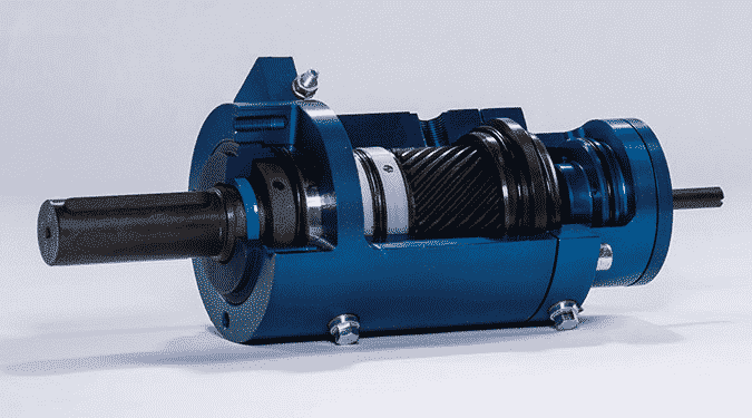
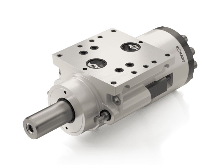
Next, determine if the rotary actuator will be used in highly dynamic applications, such as torque/torsion testing. If so, end-cushioning is important to have, along with a servo valve that can be mounted to the actuator to offer more control to the device.
End-cushioning is an important factor to consider for highly dynamic applications, such as when the actuator needs to function as an end stop in a load. End-cushioning acts as a hydraulic break to slow down the movement of the actuator so that it doesn’t slam into the end position causing damage to the device or the workpiece. The end-cushioning effect can be finely tuned using built-in orifices and set screws.
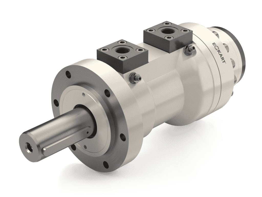
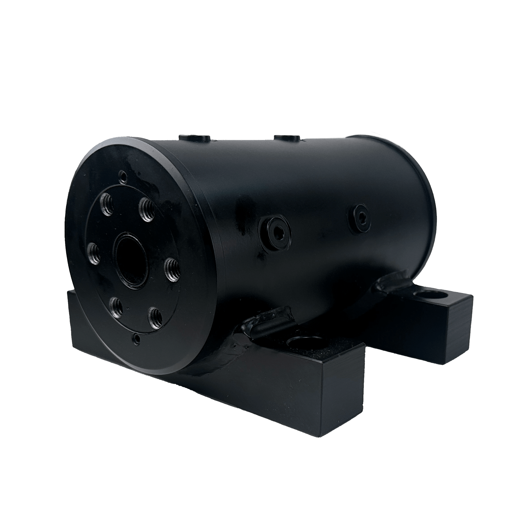
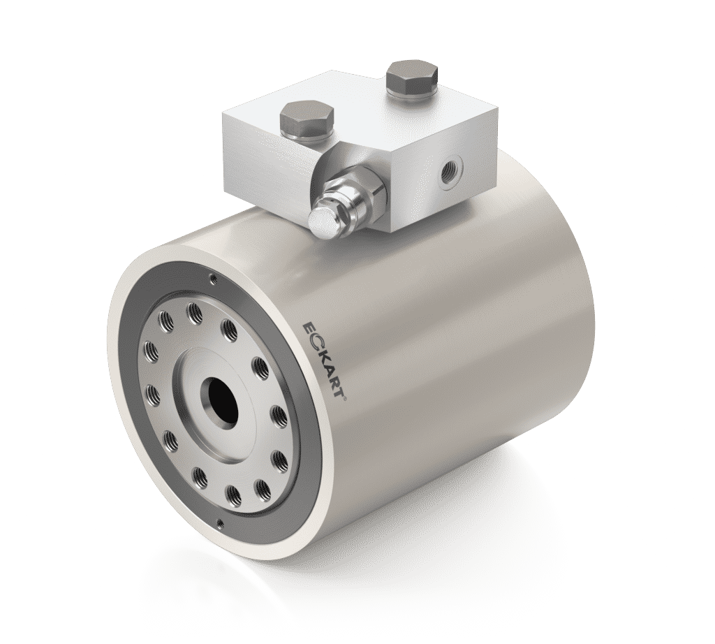
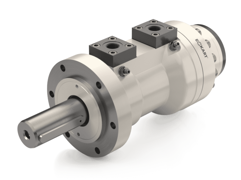
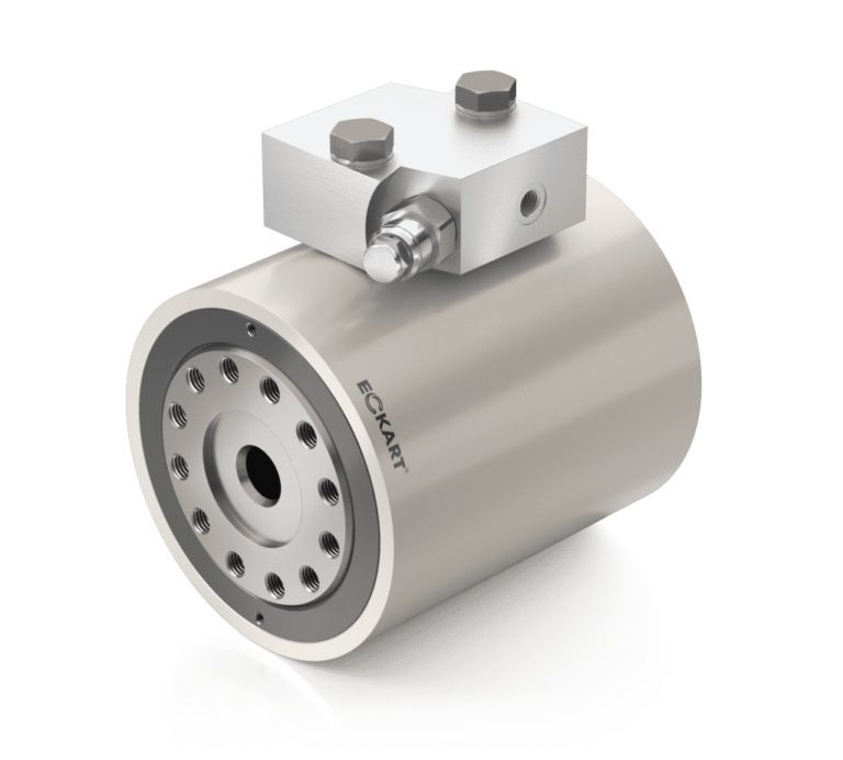
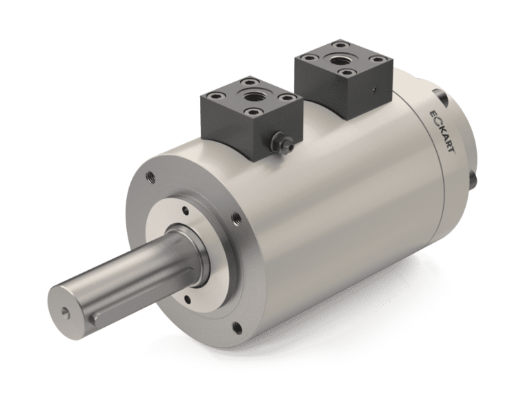
Actuators can be mounted in different ways, along with different shaft styles. The actuator might have a flange mount, foot mount, or threaded holes in the actuator body. The shaft could be male or female with spline, key, or other shapes; as well as flange style.
Typical hydraulic systems operate in an oil temperature range from -4°F to +240°F (-20°C to +60°C) in the same range. Actuators operate in the same range. If actuators need to operate above or below the standard temperature range, then special steels or special seal material may need to be used.
The same applies to different mediums. Different mediums could require non-standard seals and different actuator materials.
If the application and actuator have side loads, the side loads need be absorbed separately from the actuator, or the actuator needs to be designed to accommodate the side loads. This is often done through the use of bearings. Eckart usually includes 4-point contact bearings as standard.
Finally, it’s important to understand the general application. For example, will the device be going offshore? This might require special paint and special seals to protect the actuator from harsh seawater environments. As mentioned above, it’s important to know if the actuator will be used in testing applications, as special attention would be needed to make low-friction seals and a servo valve adapter plate.
From manipulating the angle of a boom in construction applications to opening or closing flaps in the aircraft and aerospace industries, rotary actuators are dependable and durable devices used for a wide range of uses.
Hydraulic otary actuators can function as simple tool changers. One example of this is using a rotary-linear actuator for a pallet changer that weighs 1,000 kg. This device is a combination of a rotary actuator and a dual-action linear cylinder, allowing for full flexibility in a minimal amount of space. Since the rotary actuator and the linear cylinder are hydraulically driven separately, any movement sequences can be selected: for example, rotating to the left and right, extending linearly, and retracting.
A hydraulic rotary actuator could also be used for gate valve control too. While a rotary actuator may be more expensive than pneumatic actuators, these devices have a higher level of precision, require less space, and can achieve high torque outputs. Other uses for rotary actuators include linear actuation, bending machines, work piece positioning, rotational devices, and transport applications.
One common application is using a hydraulic rotary actuator for tipping devices. A helical rotary actuator, for example, would be a suitable option for bin tippers in waste management applications due to its high torque in a compact package.
Other uses for hydraulic rotary actuators include linear actuation, bending machines, work piece positioning, rotational devices, and transport applications.